The CRT Shader in Cool Basketball Game

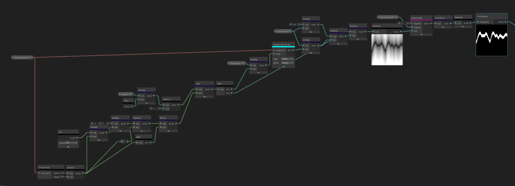
This shader was all about simulating CRT technology with the challenge of being as accurate as possible. It turns out it is just a combination of smaller effects and for a 4 week project this fit the scope well.

Warped Screen Coordinates and Vignette

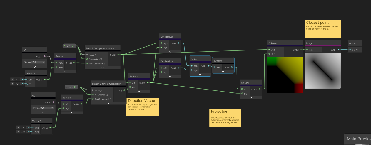
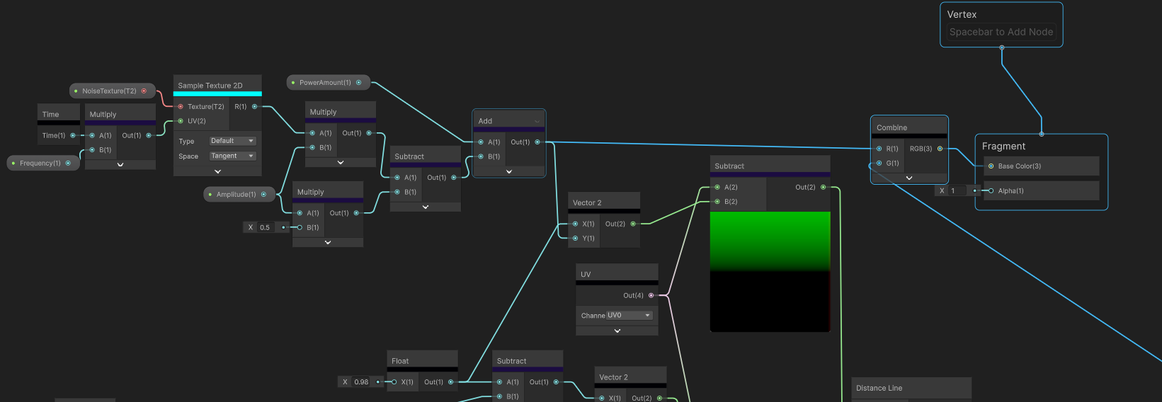
The electron beam of a CRT screen doesn’t naturally travel in a straight line which is why the screen shape is warped. CRT screens usually have a vignette around the edges to minimise the noticeable curve of the screen. Heres how I did it:

float3 CRTCoordsAndSDF(float2 p, float2 screenParams, float vignetteWidth, float warpOffset)
{
    float2 centredUV = p * 2 - 1;
    float2 warpUV = centredUV.yx / warpOffset;
    float2 uv = centredUV + centredUV * warpUV * warpUV;
    uv = uv * 0.5 + 0.5;
    
    if (uv.x <= 0.0f || 1.0f <= uv.x || uv.y <= 0.0f || 1.0f <= uv.y) uv = 0;
    
    float2 vignette = vignetteWidth / screenParams.xy;
    vignette = smoothstep(0, vignette, 1 - abs(uv * 2.0f - 1.0f));
    
    float vignetteSDF = saturate(vignette.x * vignette.y);
    
    return float3(uv, vignetteSDF);
}

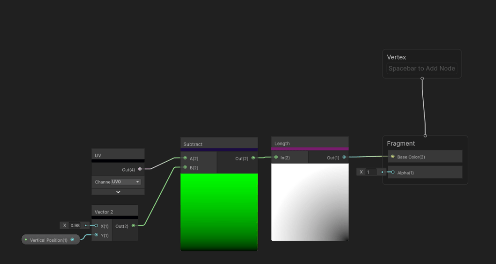
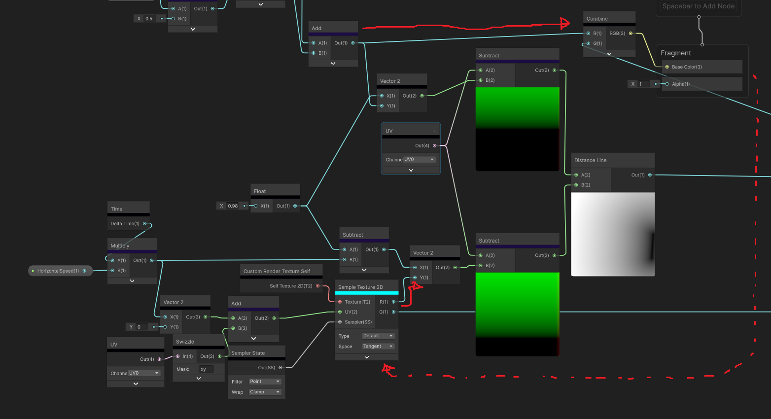
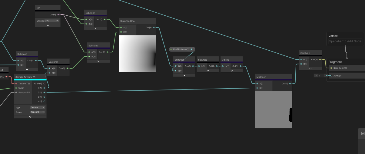
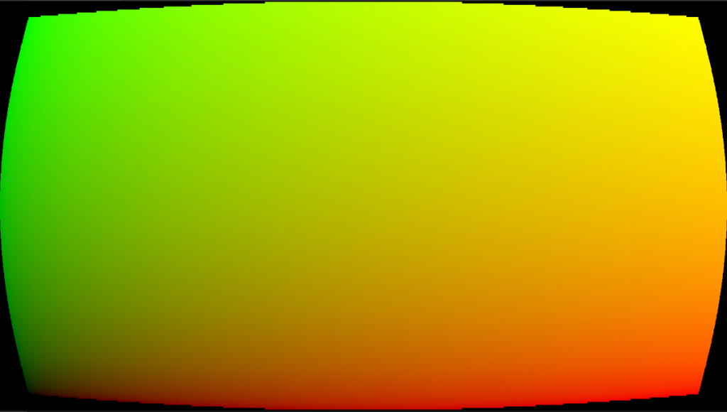
To get a curve I squared the warped UV and added back to the centred UV. I combined both the vignette and warped UV because the vignette needed the calculated UV. It was just cheaper that way. I cull out anything outside the the 0-1 range to get the shape. The UV ends up looking like this:
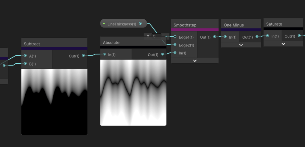
Scanlines

Scanlines are due to the horizontal raster scanning of the CRT laser beam. The laser rapidly scans one line at a time. The area between each line remain darker causing this scanline effect. I wanted control over the scanline amount and fall off. The function I use here is quite short and simple, but it does the job.

float ScanLines(float rawScale, float colValue, float scanLineFallOff)
{
    return colValue * pow(distance(frac(rawScale), 0.5), scanLineFallOff);
}

The input colValue will be the greyscale of the blit texture. This is too get brightness as a factor of the line width as brighter colours will yield thinner lines due to the bloom and colour bleeding they cause.

YIQ Colour Space

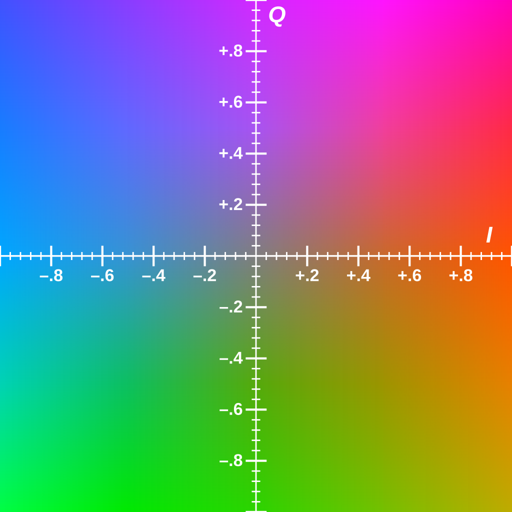
During the 1980s-1990s, broadcast television tend to use YIQ as a colour space. Y is the luminance and IQ is the chrominance. Using this colour space will constrain the colours I have available based on what was available during this period.

float3 YIQColorGrading(float3 color, float cyanToRed, float magentaToGreen, float brightness)
{
    float3x3 RGBToYIQ = float3x3(0.299, 0.596, 0.211,
                                 0.587, -0.274, -0.523,
                                 0.114, -0.322, 0.312);
    
    float3x3 YIQToRGB = float3x3(1, 1, 1,
                                 0.956, -0.272, -1.106,
                                 0.621, -0.647, 1.703);
    
    float3 colParams = float3(brightness, cyanToRed, magentaToGreen);
    float3 crtConversion = float3(0.9, 1.1, 1.5);
    
    float3 final = mul(color, RGBToYIQ);
    final = colParams + (crtConversion * final);
    
    return mul(final, YIQToRGB);
}

I found the calculations to get to YIQ on the wikipedia page . This function allows me to colour correct in the Unity scene and still output RGB values. The YIQ parameters are also public for me to use in the Unity Scene.

Chromatic Aberration and Bloom

Chromatic Aberration occurs as the electron beams age. Each beam of a CRT is either red, green or blue and all must hit the same physical point on the screen. When the accuracy wears off chromatic aberration starts to occur. These beams were prone to bloom sensitive, where lighter colours bled into neighbouring phosphor dots (CRT version of pixels). Unity’s default bloom shader sufficed well so I won’t go into much detail about that. One thing I’ll say is to replicate the CRT sensitivity, I lowered the bloom threshold. To achieve the chromatic aberration effect, I sampled the blit texture three times, each with an offset controlled in the Unity scene. One channel of each blit texture was added to a new float3, creating a similar camera texture, but with each RGB channel slightly offset from the centre of the screen.

            float chromABias = length(crtUV * 2 - 1) * _chromaticAberationIntensity;
            float3 chromCol = float3(0,0,0);
            for (int i = -offset; i <= offset; i++)
            {
                float o = chromABias * i;
                float2 uv = crtUV.xy + o;

                float4 blit = SAMPLE_TEXTURE2D_X(_BlitTexture, point_clamp_sampler, uv);
                float3 col = YIQColorGrading(blit, _cyanToRed, _magentaToGreen, _brightness);
                
                if (i== -offset)
                {
                    chromCol.x += col.x;
                }
                else if (i == 0)
                {
                    chromCol.y += col.y;
                }
                else
                {
                    chromCol.z += col.z;
                }
            }

Signal Static

Broadcast signals were prone to being unstable at times causing signal static. I use a vertical scrolling sinewave with a high frequency that changes in amplitude randomly.

float SignalSDF(float2 p, float time, float range, float freq, float mag ,float bias)
{
    float mask = 1 - saturate(range * distance(p.g, 1 - frac(time * 0.5)));
    
    float sinIn = freq * p.g;

    float b = 1 + (mask * mag * sin(sinIn));

    float wave = 1 - saturate(distance(p.r, b));
    
    float flooredTime = floor(time * 10);
    float normRandRange = Hash21(flooredTime.xx);
    float flicker = round(bias * normRandRange);
    
    float t = mask * wave * flicker;
    
    float sdf = lerp(1, 0.9, t);
    return sdf;
}

I want it to snap in an out so I floored time and put it through a Hash21 I have which will output a random value between 0-1. The bias controls how frequently the static shows on the screen.

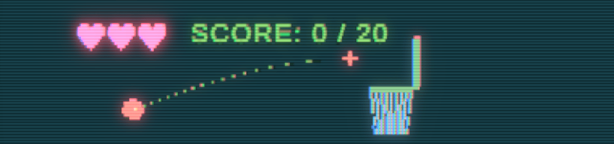
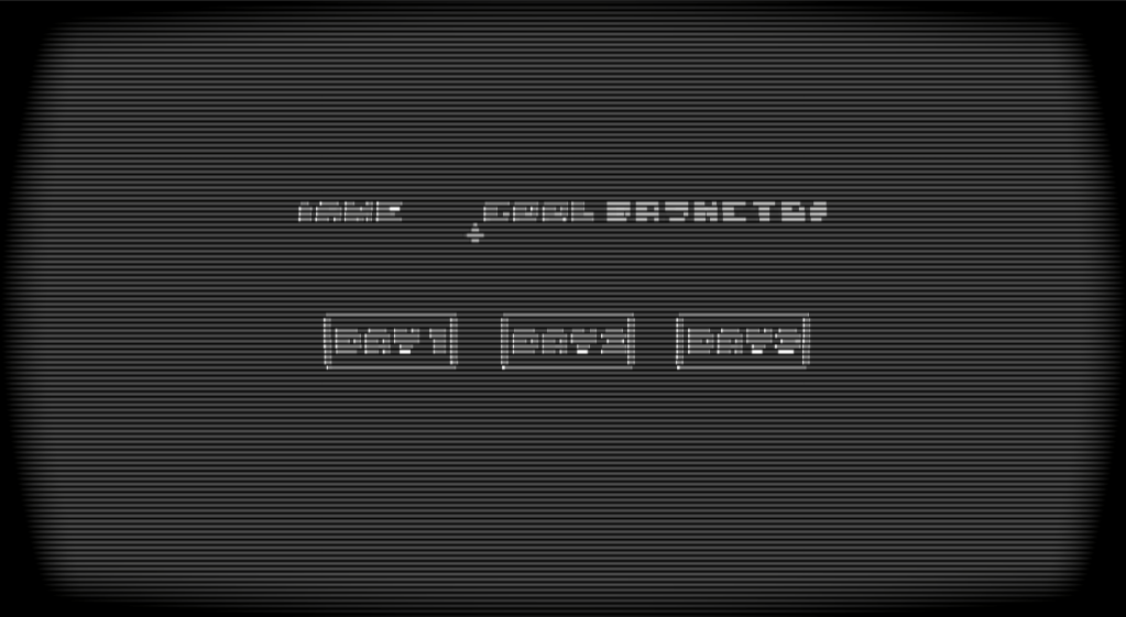
This is the final product. All fairly simple techniques here where research is the driving force for quality.

Sonar Ping Post Processing Shader

The idea behind this game is to simulate the deep sea in an abstract fashion. 80% to 90% of screen is pitch black and the colours are all on a large grid that can move with player abilities. The challenge was to still make the game legible, working with these quite extreme constraints.

This is how the scene is set. I Use the 3D render pipeline and an orthographic camera. Every material uses a flat colour and a simplified custom lighting model where all I use is the distance attenuation, and light direction to render light. This is all done in shader graph using a custom function.

void BasicAdditionalLights_half(float3 WorldPosition, float3 WorldNormal, out float TotalAttenuation, out float3 LightColor)
{
    TotalAttenuation = 0.0;
    LightColor = float3(0, 0, 0);

#ifndef SHADERGRAPH_PREVIEW
    uint pixelLightCount = GetAdditionalLightsCount();
    LIGHT_LOOP_BEGIN(pixelLightCount)

    uint perObjectLightIndex = GetPerObjectLightIndex(lightIndex);
    Light light = GetAdditionalPerObjectLight(perObjectLightIndex, WorldPosition);

    float atten = light.distanceAttenuation;

    float NdotL = saturate(dot(WorldNormal, light.direction));

    float diffuse = atten * NdotL;
    TotalAttenuation += diffuse;
    LightColor += light.color;
    LIGHT_LOOP_END

#endif
}

Too simplify it even further I use basic cell shading to get as few colours as possible for the post processing filter. Legibility is my number one priority here.

Onto the post processing, I use a Custom Render Feature because the shader I create is not possible in shader graph and optimisation is a huge factor particularly for this game.

        float4 calc(Varyings input) : SV_Target
        {
            float2 screenPos = float2(_ScreenParams.x, _ScreenParams.y);
            float2 scaledAspectRatioUV = screenPos / _gridScale;

            float2 scaledTexCoord = input.texcoord * scaledAspectRatioUV;
            float2 id = round(scaledTexCoord);
            float2 gridTexCoord = id / scaledAspectRatioUV; // quantized UV
            float4 blit = SAMPLE_TEXTURE2D_X(_BlitTexture, point_clamp_sampler, gridTexCoord);
            return blit;

I start off quantising the camera colour to retrieve this output.

Already looking tough to see. The reason why the cells need to be so big is because a black grid will need to be rendered over the top of it. Now making a grid is fairly simple and I got a video tutorial for it here. The real challenge is moving each grid cell without it loosing its square shape.

I use a compute shader to render a render texture that my post processing shader can sample.

[numthreads(8, 8, 1)]
void CSMain(uint3 id : SV_DispatchThreadID)
{
    float2 aspScreen = aspectRatioPentile(_Resolution);
    float2 uv = (float2(id.xy) + 0.5) / _Resolution;

    float2 scaledAspectRatioUV = _Resolution / _gridScale;
    float2 scaledTexCoord = uv * scaledAspectRatioUV;

    float2 idCoord = round(scaledTexCoord);
    float2 gridTexCoord = idCoord / scaledAspectRatioUV;

    float2 gridSpacePlayerPos = (_playerPos * _Resolution) / _gridScale;

    float centerLight = circleSDF(gridTexCoord, aspScreen);
    float sonarPing = sonarSDF(gridTexCoord, aspScreen, 0, 0.5);
    float flare = flareSDF(gridTexCoord, aspScreen, 20, 2) * 50;
    float radialScan = radialScanSDF(gridTexCoord, aspScreen, 1, 1) * 10;
    float col = 0;
    int neighbourRange = 4;
    for (int x = -neighbourRange; x <= neighbourRange; x++)
    {
        for (int y = -neighbourRange; y <= neighbourRange; y++)
        {
            float2 offset = float2(x, y);
            float2 localTexCoord = scaledTexCoord - offset;
            float4 currSC = float4(frac(localTexCoord), floor(localTexCoord));

            float2 localUV = (currSC.zw) / scaledAspectRatioUV;
            float sonar = sonarSDF(localUV, aspScreen, 0, 2);
            float flare = flareSDF(localUV, aspScreen, 20, 2) * 4;
            float radialScan = radialScanSDF(localUV, aspScreen, 1, 5);
            
            float totalMask = sonar + flare + radialScan;
            
            float2 displacementDir = normalize(gridSpacePlayerPos - currSC.zw);
            float2 displacedPos = currSC.xy + offset + (displacementDir * totalMask);
            float currDistFromSquare = max(-(max(abs(displacedPos.x) - 0.5, abs(displacedPos.y) - 0.5)), 0);
            col += currDistFromSquare;
        }
    } 
    float totalMask = saturate(centerLight + sonarPing + flare + radialScan);
    col = smoothstep(_gridThickness, 1 - _gridThickness, col);
    col *= totalMask;
    col = step(0.01,col);
    Result[id.xy] = float4(col, totalMask, 0, 0);
}

The way this compute shader works is I quantise the UVs to the same size as the post processing and create a mask for each type of ability that I will show later. For context I have the “Flare”, “Radial Scan” and “Sonar Ping” abilities. I make each of the SDFs and combine them all in one single mask. Then I loop through a 2D array with “offset” being each index and use that to calculate the direction the grid cell should be moving. The ability SDFs I generate determine the distance the cell will move. The larger the 2D array, the further the grid cell can travel before being culled.

It works as intended, however there is a great cost. The red flag for me is the nest for loop. Unfortunately I couldn’t find anyway of avoid the nest for loop considering I rely on a 2D array to control the direction. Along with keeping both the grid and square cell intact, made for a huge challenge. Keeping the neighbouring samples around 4 was a good balance between performance and effectiveness. Here are the other two abilties in the render texture form:

Now the mask is done I can use render texture as a multiplying factor in the UV for the blit texture.

Heres the final result with all three abilities:

In the end this was a quick solo project that tested my current capabilities as a tech artist. I feel like I stretched the what can be done here with these aesthetic and hardware limitations. For what looks to be a simplistic looking game, there’s a lot that happens underneath!

Tutorial: How to Make a Realtime Signal Graph Shader in Unity

I wanted to make a quick tutorial on using render textures in Unity and why they might be useful.

When I first started off making this shader, I started where most would start, an old fashioned Unity shader graph. It doesn’t seem too complex. Just sample a noise texture that scrolls. remap the values so the range of values is -1 to 1. then add the result to the g channel of the UV and absolute those values. Add some parameters for the amplitude, frequency and value. Here’s the shader graph:

Great!

oh no

See how the line is thinner when there’s a sudden change. That sorta sucks. The specific area of issue is this part here:

What is happening is the gradient I am outputting isn’t equal on all sides of the line. The greater the amplitude, the smaller the range between 0-1. The fix is… I don’t know… probably some crazy math that can measure the line thickness relative to the line angle. Alarm bells were ringing and I knew there was a better approach.

When I see this graph in action I imagine one of those lie detector machines that print these sorts of graphs.

Enter render textures. I wrote about these in my Creating a Fog of War Shader devlog but I’ll give a simple run down. Render textures are read and write textures that are built to be updated at runtime. GPU’s have frame length memory so the only way you can store data from the GPU is with a render texture.
So why would this help me?
Well like the lie detector graph, I can use a circle shape to use like a brush and scroll the render texture UV backwards. I like to call this the “brush stroke” method. The idea is because I use a circle shape, the line thickness is a consistent value no matter the direction of the line. I can use the “Temporal Accumulation” method here where I sample the previous frame result to affect the next frame result, which creates the brush stroke like effect. I mention this in my fog of war devlog too.

Unlike how I set up a render texture in the fog of war devlog, I wanted to try out the shader graph work flow instead of the code based work flow. The more I develop as a tech artist, the more I’m understanding the importance of learning both work flows.

To set up you need to create a “Material”, “Custom Render Texture” in the “Rendering” tab and a “Custom Render Texture” in the “Shader Graph” tab.

No idea why Unity decided to name them the exact same thing but at least you get different icons. I’ll call the shader version “Render Texture Shader Graph”. From here you set your custom render texture the same as you would with a normal texture until you get to the material. Initialization Mode I put as “OnLoad” and I put Update Mode as “Realtime”. This just made sense to me and I don’t see a use case where I would pick anything different. Color is the starting value of the render texture. This is important and it does depend on how your render texture shader graph works. The last important note is the “Double Buffered” option. This allows you to use the previous frame result of the render texture which is what I mentioned earlier.

Great. Now you can assign the render texture shader graph to the material and we can get started. Oh and also this render texture will need to be sampled in a regular material shader graph so you can actually see it in the game.

To get things started I like to separate everything into small easy steps and see the output in game at each step. The first step is to create a make the brush shape and put it in the correct position.

From there I scroll a noise texture to randomly offset the vertical position over time and add in some public parameters.

A little technique that I use everywhere to remapping a value cheaply is what I do with the “Amplitude” parameter. If you know the original range is between 0-1 and you want to extend the range while keeping 0 in the middle, you can multiply the parameter by the 0-1 texture, then subtract half the parameter. Say the amplitude value is 3, the result would be a range between -3 and 3. Everything else is using basic offset, scale and rounding functions for better control.

Now for the temporal accumulation.

The new node for me at least is the “Custom Render Texture Self” node which is the previous frame render texture and you treat it like any other texture. It defaults to bilinear filtering even though I set the custom render texture filtering to point so I have to override that using the sampler state node. The main focus is how I set the UV. I add a very small constant value on the x axis. If I keep that a hard coded number, the graph works. Now every frame this shader will compare the calculated shader to the previous result and pick the smallest texel drawing a line. However, a very crucial and often forgotten component is adding in GPU frame independence. In other words, I don’t want the FPS to dictate the speed of the graph. Unity supplies the delta time value already. If I use that updating value instead, it will no longer matter what your FPS is, thus the graph will run at a constant speed.

Nice.

Now this is much better, but pushed to the brink, the shader still breaks.

I still get this amplitude problem. As a game dev I come to the very naturally choice between fixing it or letting it be.

I had one idea. What if instead of drawing dots, I draw lines? I already know the coordinate of each point, so just connect the dots.

I have another very handy technique I use that does exactly this. This is the sub graph I take to almost every project that I called “Distance Line”.

I got this math from a Shadertoy shader and I’ll admit, I still don’t quite understand the math here. I’ll link the shader below. The inputs are two UVs. The output is a linear line between the two origin points of the UVs.

So to connect the dots, I need more information coming from the previous frame render texture or more specifically the last y value that was calculated. This is the 0-1 value that makes the brush wobble up and down randomly. I store that value directly into the R channel to use later. I also use this value to set the y origin of the next UV.

Then I get that same y value to recalculate the previous UV. These two UVs are the inputs to my Distance Line node I showed earlier.

I also used the delta time value as the horizontal offset for the second UV because that is the exact x position of the tail of the line.

Then its just the same temporal accumulation pattern as before where I reuse the G channel.

Looks like it passes the stress test.

Its weird how often seemingly simple shaders turn into something much more complex and how they uncover hardware limitations. This is such a tiny part of this game and this game I’m making is a relatively small game. However, what lies underneath, is a whole system using a custom render texture graph that uses temporal accumulation and distance lines that is then sampled again through a material shader to output to the screen. I find this sort of stuff so fascinating, because to the player, they will never know.

Anyways, I hope to continue these blogs. As go continue my development as a tech artist. See you guys later.

Distance Line Shader: https://www.shadertoy.com/view/WddGzr