
Traitors on the Train
Sun SDF
Moon SDF
Music Note Particles
Sleeping Zs
Speech Bubble Particle
Fun Stuff
Sun SDF
Moon SDF
Music Note Particles
Sleeping Zs
Speech Bubble Particle
I went through quite a few iterations for my custom particle system to support all the features I wanted in my game. There was a lot to handle. Juggling particles, procedural meshes, sprites and textures, along with an editor tool and render feature.
Why custom made?
Unity offers VFX graph for particle systems and could have been some what viable for what I wanted. It supports custom attributes, bitwise operations and most importantly compute buffers. Where it falls short for me is, it’s node based. Now I do love node based work flows… but for simple shaders and systems. It allows easy things to be easier, but makes thing hard things harder. I have a total of 9 compute buffers for my particle system thus far. Too much to handle without some insane spaghetti graphs and not something VFX graph was really built for. Another reason why is because, I just love learning. Coming out of finishing this system, I realise so much possibility and understanding of the hardware I am working with. I now see the work I did for Helm of Heresy is barely scratching the surface of what it truly possible when it comes to compute shaders.
The Broadview of the System
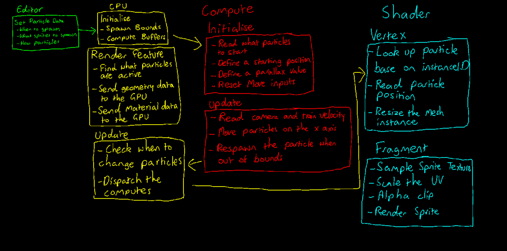
There are 4 main components to my custom particle system. In editor, I write to a scriptable object to blue print all the particle data to send to my spawner script at runtime. I decide what sprites to spawn, how many and when they should spawn. In Traitors on the Train, the environment updates whenever the player checks a ticket, so I treat the ticket check count time. Doesn’t quite replicate reality, but hey, its a video game after all. When the scene first loads, I define the spawn bounds which is the area the camera is bounded too and create all my compute buffers that store various arrays of data for the GPU to read. Over to the Render Feature, I procedurally generate quad meshes for my shader to receive and only generate quads based on the current particles that are set. Finally on the CPU at runtime, I send an event each time the player checks a ticket for the spawner to listen too and update the compute buffers and material data based on the data i defined in my editor tool. I also dispatch the compute results for my shader to read. On the GPU side, the compute shader starts by defining a start position and parallax value and then on update, reading the camera and train velocity, I scroll every active particle across the spawn bounds. Finally on the shader side I resize the quad based on the sprite data and position the quad based on the particle data. On the fragment side, I sample the material’s texture, alpha clip and render the sprite.
Editor Tool
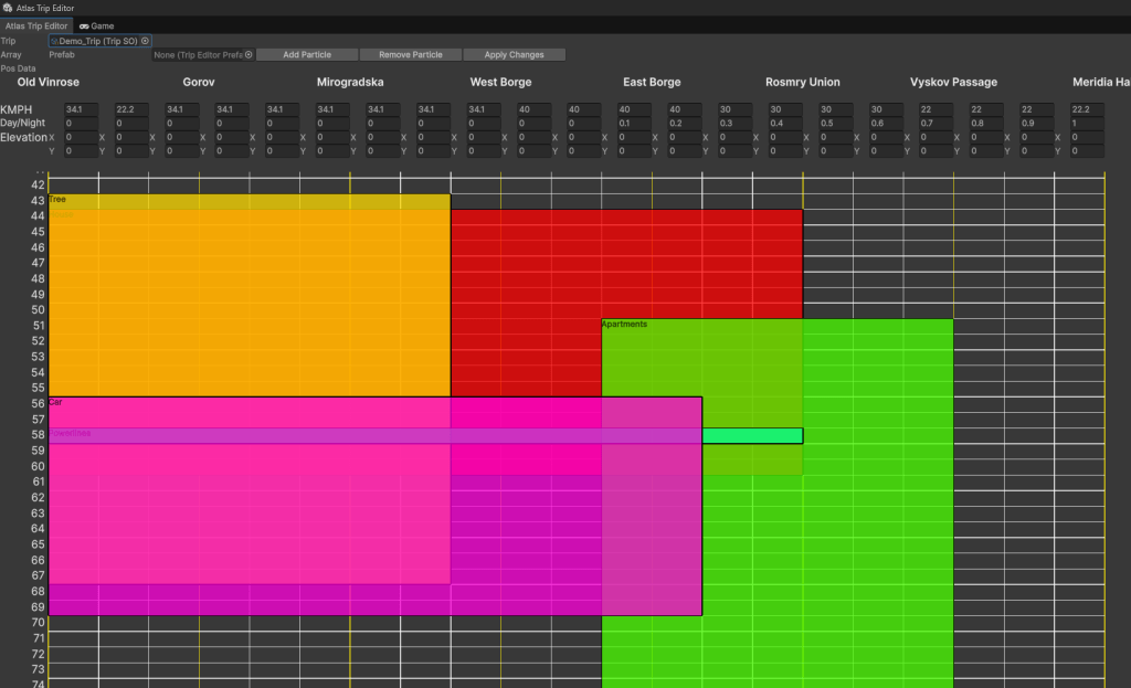
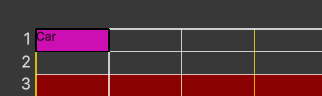
I developed an editor tool dubbed, “Atlas Trip Editor”. I knew early on I needed some sort of timeline interface so I can easily adjust what sorts of particles I want to render. There are a lot of parameters to handle. Having it all in one place helped streamline the workflow. I start with the Trip scriptable object. Trips are essential levels, but because my game is procedural, the the is no manually building the level architecture in the scene. I literally spawn everything at runtime.
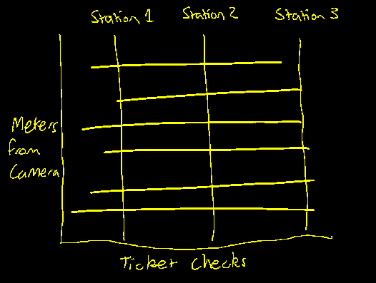
So the basic Idea is on the Y axis I have the meters from the camera. Additionally I mark where the tracks and train line should spawn. I also mark the area red where the train is so I don’t spawn things that would go through the train. On the x axis is where I mark the ticket checks treating that as if it’s time.
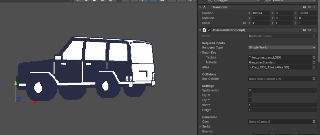

To add a particle, I first create a dummy prefab. I realise a lot of the sprite data can be read directly off my custom renderer. You can read all about that system here. I can get the texture, atlas, sprite index, width and height. I place the prefab file in the prefab slot and click add particle.
This block I call “Pos Data” already has all the sprite information so now I just need to define how many to spawn, when and where to spawn.
You will also notice a particle type option where is says “Simple”. I have two other options “Tiled” and “Sliced”. Tiled would meaning I render one quad and repeat the texture. I use this for my train tracks and train lines. Sliced is for nine sliced sprites, where I give a random width and height to the sprite. This is how a get random shaped buildings that still have edges.
This is an older version of the tool while it was still in it’s testing phase, but you can see how the graph translates to the scene. This took a lot of computational power to I removed this feature of the tool. It wasn’t too important in the end anyways so it wasn’t worth the time to optimise.
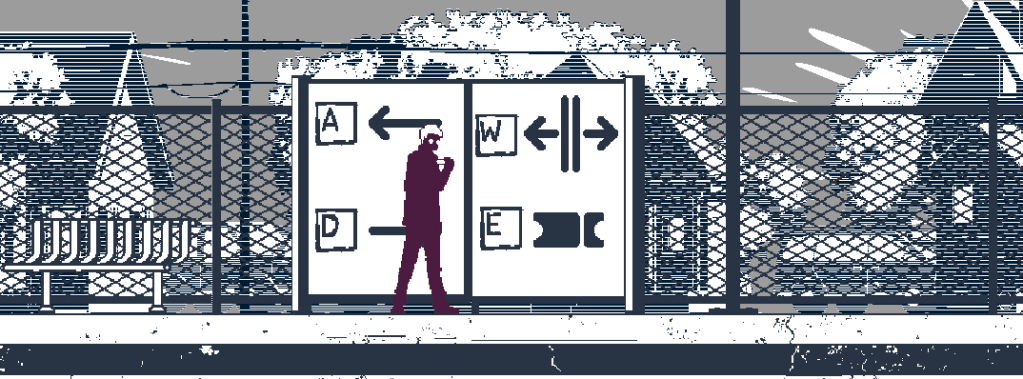
This is the final look. Here you can see at runtime, when the player checks a ticket, the trees stop spawning and the buildings scroll in. I will say this is the most complicated system I have built and this was only a brief overview. This is something I am quite proud of.
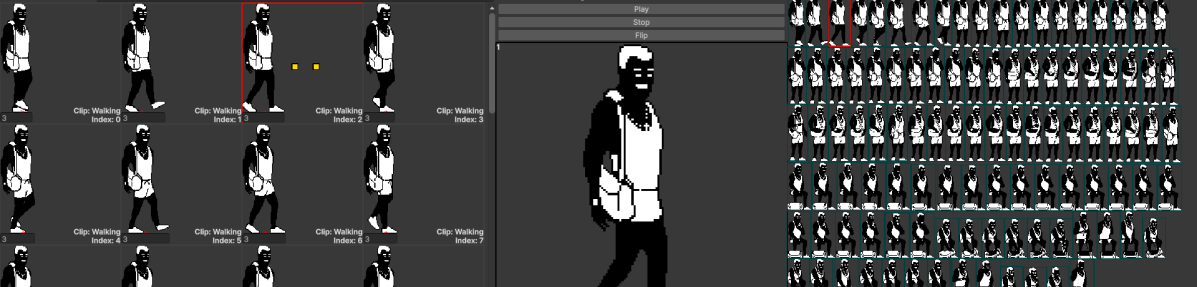
Hello. This is my Sprite and Animation system I built for Traitors on the Train. The video above is a walkthrough of the workflow but here I will show the inner workings of it all.
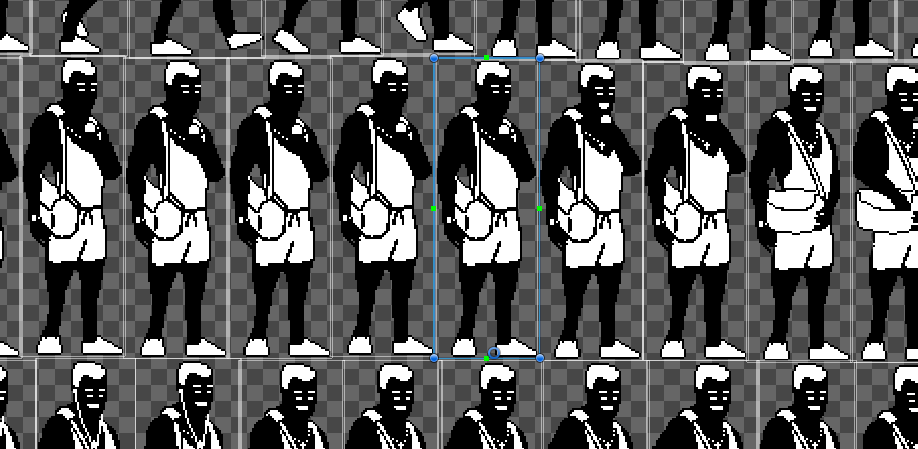
Defining pivot points in a sprite animation workflow is also a difficult task. Unfortunately, you cannot simple import a animated file into Unity. Instead you import an atlas where you have to the pivot points manually. I have 104 sprites for this one NPC and I’m aiming for 60 NPCs in Traitors on the Train. That’s about 6000 sprites and therefore 6000 pivots. Alternatively you can align your sprites in grid cells. Each grid cell would be the same size and you orient the sprite basing the bottom center of the grid cell to be your pivot. You would have to place the sprite in a pixel perfect position otherwise the animation would jitter at run time.
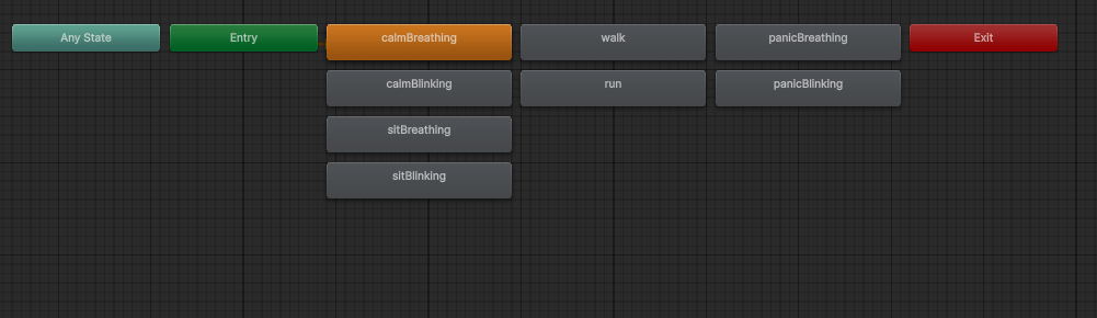
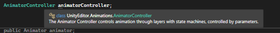
I’ve always dislike Unity’s Animator. It felt like it was playing the role of the middle man. I assume the Animator was built for 3D rather than 2D, but tries to cater for both. The generic structure of the tool left me with pointless features and missing features I needed in my specific context and workflow. I much rather use code over visual scripting and the Animator felt like a poor version of visual scripting. In code the animator cannot be accessed at runtime because that class lives in the Editor library, meaning these state nodes cannot be access directly at runtime. Sometimes I needed those states. The workaround was to access the data I needed in another editor script and store that data in a scriptable object somewhere. I always felt like I was fighting against the animator rather than it helping me.
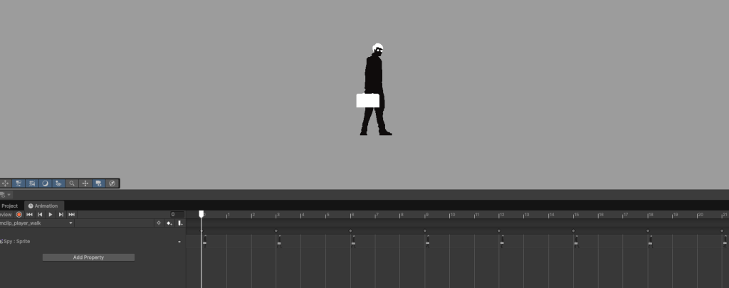
The animation clip system was also a bit of a thorn in my workflow. I assume this is how Unity wants developers to set up the workspace. You put the Animation clip window at the bottom and the scene window at the top and adjust the keyframe from there. I have a lot of animations plus building the rest of the game. When I get an animatable game object in my project I just want to open a window and do it there, not do this set up. Sometimes I may not have a prefab ready for this too. I could work with it, but every time I set some animations up, I always felt like there was a better way for me.
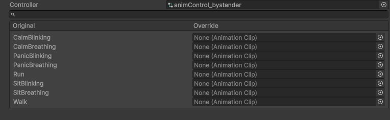
Okay this was annoying too. Animation Override Controllers. Each NPC had the same animation states but different animation clips. This should be an easy one to solve… nope. You make an animation override controller for each NPC and then assign each clip here. And then this override controller acts as the animation controller in the Animator component. Lots of clicking and dragging. I used to dread this part because I felt like setting up the animation clips were the only things I should be setting up. Knowing what I know now, I would’ve built some sort of editor tool that would read the file name and automatically assign the clips, because it was the same process every time.
    [Serializable] public struct MarkerKey
    {
        public Color32 color;
        public MarkerType type;
    }
    [Serializable] public struct MarkerPosition
    {
        public Vector2 objectPos;
        public MarkerType type;
    }
    [Serializable] public struct SimpleSprite
    {
        public Vector4 uvSizeAndPos;
        public Vector2 uvPivot;
        public Vector3 worldSize;
        public int index;
    }
    [Serializable] public struct MotionSprite
    {
        public SimpleSprite sprite;
        public MarkerPosition[] markers;
        public int holdFrames;
    }
So almost always, when I build systems, I start by defining data structures that I may need. Overtime these will change, depending on how the system evolves but starting here helps me ground myself to the data. The question is simple, “what is a sprite?”. The answer is defined in the screenshot above, a UV size and position. A single vector4 is the bare bones. Where is the sprite in the texture and how big. From there I eventually needed another vector2 for a pivot, a world size and index in the texture. You can see I start to stack these data structures together making specific types, like the motion sprite, which needs everything a simple sprite has however it also needs a marker position which I talk about in the video and how long it holds its frame in the animation.
public class AtlasSO : ScriptableObject
{
    public Texture2D texture;
    public Color32 spriteConnectColor = Color.clear;


    [Header("Motion Settings")]
    public EntityMotionType entityMotionType;
    public Color32 pivotColor = Color.clear;

    [Header("Sliced Settings")]
    public Color32 sliceColor = Color.clear;

    [Header("Generated")]
    public MotionSprite[] motionSprites;
    public SimpleSprite[] simpleSprites;
    public SliceSprite[] slicedSprites;
    public AtlasClip[] clips;
    public MarkerKey[] markers;

    public Dictionary<int, AtlasClip> clipDict;

    public void UpdateClipDictionary()
    {
        clipDict = BuildClipKeys(clips);
    }
}
From there I store these sprites in a scriptable object I call AtlasSO. For each sprite atlas texture, one of these created with it. There’s lots of types of textures so this scriptable object got pretty generic.
To render anything in a game, a material and mesh needs to exist. I’m making a 2D game which is fortunate for me because every mesh is a quad made up of two triangles. I could not use Unity’s sprite renderer because I am defining my own sprites. So now a custom renderer is needed which means, I would need to make my own render pipeline. I’m glad this was eventually worth it.
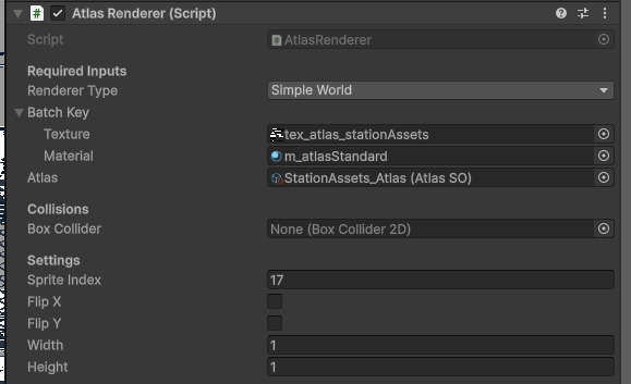
So on the game object scope, I need a rendering component I call my “Atlas Renderer”. It requires a type, a texture, a material and an AtlasSO. In the Settings, I have a sprite index, flip options and sizing options.
    public void UpdateSpriteInputs(SimpleSprite newSprite)
    {
        sprite = newSprite;
        spriteIndex = newSprite.index;
        worldPivotAndSize.z = newSprite.worldSize.x;
        worldPivotAndSize.w = newSprite.worldSize.y;
        uvSizeAndPosition = newSprite.uvSizeAndPos;

        scaleAndFlip.x = width;
        scaleAndFlip.y = height;

        spriteIndex = sprite.index;
        FlipHSimple(flipX);
        FlipVSimple(flipY);
        SetBounds();


        if (boxCollider == null) return;
        boxCollider.size = bounds.size;
        boxCollider.offset = bounds.center - transform.position;

    }
In my Atlas Renderer I need to pass in the information from the AtlasSO to the renderer itself to store. The renderer component does two main things. It stores data of the current sprite it is rendering and subscribes itself to a Sprite batch. Now renderer components in 2D, don’t actually render the object. In fact, it acts as a container for the Render Feature to eventually render the sprite. I’ll explain below.
So there’s more context to get through before I move on. On modern GPU hardware, we can use batching techniques to render sprites. This means, instead of telling the CPU to render each sprite one draw call at a time, we can instead render batches of them but there are requirements. You would notice earlier, in the inspector I have a struct called “BatchKey”. As long as the texture and the material match those sprites can be rendered within a single draw call.
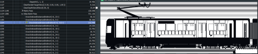
In this image on the 1204th draw call, the entire train rendered in 232 microseconds. That’s 31 sprites in this example. To do this I have a list and a dictionary. The Batch key is used as the key and the Sprite Batch is the value.
    public class SpriteBatch
    {
        public List<AtlasRenderer> atlasRendererList = new List<AtlasRenderer>();

        public SpriteData[] spriteData = new SpriteData[MAX_SPRITE_DATA_COUNT];

        public GraphicsBuffer spriteDataBuffer;
        public GraphicsBuffer argsBuffer;

        public MaterialPropertyBlock mpb;
    }
Sprite Batches contain the list of renderer components to render, an array of sprite data to assign the the sprite data buffer, an args buffer for the renderer feature to read and a material property block. Okay. To reiterate, this Sprite Batch represents that draw call from the image eariler.
    private void OnEnable()
    {
        if (batchKey.texture == null) return;
        batchKey.texture = atlas.texture;
        RegisterRenderer(this);
    }
    public static void RegisterRenderer(AtlasRenderer renderer)
    {
        if (renderer.batchKey.material == null) return;
        renderer.batchKey.material.enableInstancing = true;

        UnregisterRenderer(renderer);

        if (!spriteBatchDict.TryGetValue(renderer.batchKey, out SpriteBatch batch))
        {
            batch = new SpriteBatch();
            batch.spriteDataBuffer = new GraphicsBuffer(GraphicsBuffer.Target.Structured, MAX_SPRITE_DATA_COUNT, SPRITE_DATA_STRIDE);
            batch.argsBuffer = new GraphicsBuffer(GraphicsBuffer.Target.IndirectArguments, 1, ARGS_STRIDE);
            batch.mpb = new MaterialPropertyBlock();

            spriteBatchDict.Add(renderer.batchKey, batch);
        }

        batch.atlasRendererList.Add(renderer);
    }
Now the Atlas Renderer component registers itself when it’s enabled. It also unregisters itself when it’s disabled so the sprite stops rendering. The function above checks to see if the batch key already exists in the dictionary. If it does, it adds itself to the batch list to be rendered otherwise it creates a new batch and slots itself there.
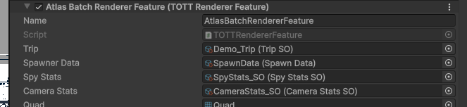
In my 2D Universal Render Pipeline Asset_Renderer I add a new Render Feature I’m calling TOTT (Traitors on the Train) Renderer Feature.

In Unity 6 you can inherit from ScriptableRendererFeature and work with Unity’s render graph system. This is where I sorta let Unity take the wheel and use their API here.
    private class AtlasBatchPass : ScriptableRenderPass
    {
        private static CameraStatsSO cameraStats;
        private static Mesh quad;
        private uint[] args;

        public AtlasBatchPass( CameraStatsSO camStats, Mesh quadToUse)
        {
            renderPassEvent = RenderPassEvent.AfterRenderingOpaques;
            cameraStats = camStats;
            quad = quadToUse;
        }

        public override void RecordRenderGraph(RenderGraph renderGraph, ContextContainer frameData)
        {
            UniversalResourceData resources = frameData.Get<UniversalResourceData>();

            using IRasterRenderGraphBuilder builder = renderGraph.AddRasterRenderPass<AtlasPassData>("Atlas Batch Pass", out AtlasPassData passData);
            passData.cameraStats = cameraStats;
            builder.SetRenderAttachment(resources.activeColorTexture, 0);
            builder.SetRenderAttachmentDepth(resources.activeDepthTexture, AccessFlags.ReadWrite);
            builder.AllowPassCulling(false);

            args = new uint[5]
            {
                quad.GetIndexCount(0),
                0,
                quad.GetIndexStart(0),
                quad.GetBaseVertex(0),
                0
            };

            builder.SetRenderFunc((AtlasPassData data, RasterGraphContext ctx) =>
            {
                ExecuteBatch(ctx.cmd, data.cameraStats, quad, ref args);
            });
        }
First I create a scriptable render pass which is where I hold my quad mesh. Like I was saying before sprite is a quad so I only need to hold one instance of it, which is why the mesh lives in the render pass. Then I use the RecordRenderGraph override function to define my args buffer array and subscribe my execute batch call to the render functions.
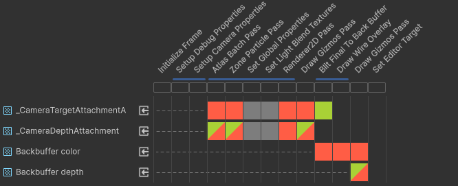
In the render graph viewer, the pass will show there.
Now for some nesting. I loop through each batch that exists and from each batch I loop through each renderer component reregistered to that batch. I’ll ignore the editor stuff. Thats just for prefab viewing.
        private static void ExecuteBatch(RasterCommandBuffer cmd, CameraStatsSO camStats, Mesh quad, ref uint[] args)
        {
#if UNITY_EDITOR
            PrefabStage prefabStage = PrefabStageUtility.GetCurrentPrefabStage();
            Scene prefabScene = default;
            if (prefabStage != null) prefabScene = prefabStage.scene;
#endif
            foreach ((BatchKey key, SpriteBatch data) spriteBatch in spriteBatchList)
            {
                int count = 0;
                for (int i = 0; i < spriteBatch.data.atlasRendererList.Count && count < MAX_SPRITE_DATA_COUNT; i++)
                {
                    AtlasRenderer renderer = spriteBatch.data.atlasRendererList[i];

                    if (renderer == null || !renderer.gameObject.activeInHierarchy) continue;
#if UNITY_EDITOR
                    if (prefabStage != null) { if (renderer.gameObject.scene != prefabScene) continue; }
#else
                    if (renderer.bounds.max.x < cameraStats.camWorldLeft || renderer.bounds.min.x > cameraStats.camWorldRight || renderer.bounds.max.y < cameraStats.camWorldBottom || renderer.bounds.min.y > cameraStats.camWorldTop) continue;

                    renderer.UpdateBounds();

                    switch (renderer.rendererType)
                    {
                        case AtlasRendererType.SimpleWorld:
                        case AtlasRendererType.MotionWorld:
                        {
                            SpriteData spriteData = spriteBatch.data.spriteData[count];

                            spriteData.worldPosition = renderer.transform.position;
                            spriteData.worldPivotAndSize = renderer.worldPivotAndSize;
                            spriteData.uvSizeAndPos = renderer.uvSizeAndPosition;
                            spriteData.scaleAndFlip = renderer.scaleAndFlip;
                            spriteData.custom = renderer.custom;
                            spriteData.customBit = renderer.customBit;
                            spriteBatch.data.spriteData[count] = spriteData;
                            count++;
                        }
                        break;

                        case AtlasRendererType.SliceWorld:
                        {
                            for (int j = 0; j < renderer.worldPivotsAndSizes.Length; j++)
                            {
                                SpriteData spriteData = spriteBatch.data.spriteData[count];

                                spriteData.worldPosition = renderer.transform.position;
                                spriteData.worldPivotAndSize = renderer.worldPivotsAndSizes[j];
                                spriteData.uvSizeAndPos = renderer.uvSizesAndPositions[j];
                                spriteData.scaleAndFlip = renderer.scalesAndFlips[j];
                                spriteData.custom = renderer.customs[j];
                                spriteData.customBit = renderer.customBit;
                                spriteBatch.data.spriteData[count] = spriteData;

                                count++;
                            }
                        }
                        break;
                    }
                }...
Then the renderer pass its data to the sprite data array. Note that for nine slicing, each sliced quad would be its own Sprite Data element which is why I had to split between each type.
                if (count == 0) continue;

                spriteBatch.data.spriteDataBuffer.SetData(spriteBatch.data.spriteData, 0, 0, count);
                args[1] = (uint)count;
                spriteBatch.data.argsBuffer.SetData(args);
                spriteBatch.data.mpb.SetBuffer("_SpriteData", spriteBatch.data.spriteDataBuffer);
                spriteBatch.data.mpb.SetTexture("_AtlasTexture", spriteBatch.key.texture);
                cmd.DrawMeshInstancedIndirect(quad, 0, spriteBatch.key.material, 0, spriteBatch.data.argsBuffer, 0, spriteBatch.data.mpb);
finally I set the buffers and texture to the matieral property block and use Unity’s DrawMesgInstancedIndirect to send over the data to the GPU to render.
So the shader cannot be made in shader graph because structs and structured buffers are not available so I write everything in Unity’s shader lab instead.
            struct Attributes
            {
                float4 positionOS : POSITION;
                float2 uv : TEXCOORD0;
                uint instanceID : SV_InstanceID;
            };

            struct Varyings
            {
                float4 positionHCS : SV_POSITION;
                float2 uv : TEXCOORD0;
                uint instanceID : TEXCOORD1;
                float3 worldPos : TEXCOORD2;
            };

            StructuredBuffer<AtlasSprite> _SpriteData;

            TEXTURE2D(_AtlasTexture);
            SAMPLER(sampler_AtlasTexture);
To start my Attributes and Varyings have nothing special in them. Although one thing to note is the instanceID is the index of the batch. Just below is my StructuredBuffer that hold my AtlasSprites which is just a custom struct I have. Looks like this:
struct AtlasSprite
{
    float4 position;
    float4 pivotAndSize;
    float4 uvSizeAndPos;
    float4 scaleAndFlip;
    float4 custom;
    int customBit;
};
This is an identical struct to my SpriteData but now defined on the GPU. I sort of wished I kept the naming consistent. Oh well.
Because I am defining my instances in the SpriteData, there is no need for a c buffer like you would with a typical shader lab shader. All I have is instanced data or global data. To keep both batching intact and creative flexibility I have a float4 called custom and an int called customBit. So if I want to change parameters on the sprite I can whilst keeping the sprite batched. I don’t think Unity can do this.
                int bitMask = i.customBit;

                int diagonalMask = saturate(bitMask & DIAGONAL_TEXTURE_BIT);
                half diagonal = diagonalTex.r * diagonalMask;


                half3 col = i.custom.rgb + diagonal;
                half t = round(LinearLightness(col));

                int meridiaColorMask = saturate(bitMask & MERIDIA_COLOR_BIT);
                float3 meridiaColor = meridiaColorMask * _MeridiaColor;

                half3 finalCol = lerp((blackTex + col) * border + _BlackColor + meridiaColor, whiteTex * col + _BlackColor + meridiaColor, t);
An example is this shader here, where I use the custom float4 as an rgb color and the customBit to turn on and off a texture.
            Varyings vert(Attributes v)
            {
                Varyings o;

                AtlasSprite spriteData = _SpriteData[v.instanceID];


                float3 position = spriteData.position.xyz;

                float2 pivot = spriteData.pivotAndSize.xy;
                float2 size = spriteData.pivotAndSize.zw;

                float2 scale = spriteData.scaleAndFlip.xy;
                float2 objPos = v.positionOS.xy;

                objPos *= size * scale;
                objPos += pivot;

                float3 worldPos = float3(position.xy + objPos, position.z);
                o.worldPos = worldPos;
                o.positionHCS = TransformWorldToHClip(worldPos);
                o.uv = v.uv;
                o.instanceID = v.instanceID;

                return o;
            }

            half4 frag(Varyings i) : SV_Target
            {
                uint id = i.instanceID;
                AtlasSprite spriteData = _SpriteData[id];

                float2 uvSize = spriteData.uvSizeAndPos.xy;
                float2 uvPos = spriteData.uvSizeAndPos.zw;

                float2 scale = spriteData.scaleAndFlip.xy;
                float2 flip = spriteData.scaleAndFlip.zw;

                i.uv *= scale;
                i.uv = frac(i.uv);
                i.uv = (i.uv - 0.5) * flip + 0.5;
                i.uv *= uvSize;
                i.uv += uvPos;

                half4 color = SAMPLE_TEXTURE2D(_AtlasTexture, sampler_AtlasTexture, i.uv);

                half grey = color.r + (-(_DayNight * 1.1 - 0.9) * _DayNightFactor);
                half3 finalColor = grey + _BlackColor;

                float2 worldToTrain = (i.worldPos.xy - _TrainBoundsMin.xy) / _TrainBoundsSize.xy;
                half4 carriageSDF = SAMPLE_TEXTURE2D(_CarriageBoundsTexture, sampler_CarriageBoundsTexture, worldToTrain);
                float bayer = BayerX8(carriageSDF.r + 0.5,  i.positionHCS.y);

                float outside = max(step(worldToTrain.x, 0.0), step(1.0, worldToTrain.x));
                outside = max(outside,max(step(worldToTrain.y, 0.0),step(1.0, worldToTrain.y)));
                outside = max(outside, step(_TrainBoundsMin.z,i.worldPos.z));
                float alpha = max(bayer, outside) * color.a;

                clip(alpha - 0.001);
                return half4 (finalColor, 1);
            }
            ENDHLSL
Back to the standard shader. I use the world position of the component, and the sprite data so finally crop the sprite on the quad.
So again I’ll start with the Data structures. The Atlas Clip struct hold a type which is either loop, ping pong, one shot or manual as I discussed in the video. It also holds a motion index so I can look it up easily in the clip dictionary, a keyframe start and end.
    [Serializable] public struct AtlasClip
    {
        public string clipName;
        public ClipType clipType;
        public int motionIndex;
        public int keyframeStartIndex;
        public int keyframeEndIndex;
    }
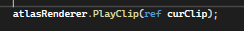
At runtime I call PlayClip shown below.
    public void PlayClip(ref AtlasClip clip, Transform markerTransform = null)
    {
        if (clip.motionIndex != curMotionIndex)
        {
            curFrameIndex = clip.keyframeStartIndex;
            curMotionIndex = clip.motionIndex;
        }
        MotionSprite motionSprite = GetNextKeyframeIndex(atlas, clip, ref keyframeClock, ref curFrameIndex, ref prevFrameIndex);

        if (motionSprite.sprite.index == sprite.index) return;

        if (markerTransform != null && motionSprite.markers.Length > 0)
        {
            Vector3 markerPos = motionSprite.markers[0].objectPos;
            if (flipX) markerPos.x *= -1;
            markerPos.z = markerTransform.localPosition.z;
            markerTransform.localPosition = markerPos;
        }
        sprite = motionSprite.sprite;
        UpdateSpriteInputs(sprite);
        isAnimating = true;
    }
It waits until the next sprite is ready to render within the clip and updates the renderer accordingly.
    public static MotionSprite GetNextKeyframeIndex(AtlasSO atlas, AtlasClip clip, ref float keyframeClock, ref int curFrameIndex, ref int prevFrameIndex)
    {
        if (curFrameIndex > clip.keyframeEndIndex || curFrameIndex < clip.keyframeStartIndex) curFrameIndex = clip.keyframeStartIndex;

        keyframeClock += Time.deltaTime;

        MotionSprite curMotionSprite = atlas.motionSprites[curFrameIndex];
        int curFrame = (int)(keyframeClock * FRAMES_PER_SEC);

        if (curFrame < curMotionSprite.holdFrames) return curMotionSprite;

        switch (clip.clipType)
        {
            case ClipType.Loop:
            {
                prevFrameIndex = curFrameIndex;
                curFrameIndex++;

                if (curFrameIndex > clip.keyframeEndIndex)
                {
                    curFrameIndex = clip.keyframeStartIndex;
                }

                keyframeClock = 0;
            }
            break;
            case ClipType.PingPong:
            {
                if (curFrameIndex < clip.keyframeEndIndex && (curFrameIndex > prevFrameIndex || curFrameIndex == clip.keyframeStartIndex))
                {
                    prevFrameIndex = curFrameIndex;
                    curFrameIndex++;
                }
                else
                {
                    prevFrameIndex = curFrameIndex;
                    curFrameIndex--;
                }
                keyframeClock = 0;
            }
            break;
            case ClipType.OneShot:
            {
                prevFrameIndex = curFrameIndex;
                if (curFrameIndex < clip.keyframeEndIndex)
                {
                    curFrameIndex++;
                }
                keyframeClock = 0;
            }
            break;
        }

        return atlas.motionSprites[curFrameIndex];
    }
GetNextKeyFrameIndex is where most of the work happens. It increase the keyframeClock until it reaches the current motion sprite’ hold time. It checks what clip type the motion sprite is apart of and returns the next motion sprite.
On the interface all it looks like is this called in the Update loop.
Its funny how a sprite has so much happening under the hood. Two triangles. This blog followed the inner workings of at least my rendering system. Unity doesn’t show theirs but I imagine this would be close to it with some added features I needed.
See ya later.
Hello. In this devlog I want to talk about my NPC system. Before I jump into the code I want to establish some context. In my game “Traitors on the Train”, NPCs are integral to the gameplay loop. The player who acts as a ticket inspector but is secretly a spy must check tickets of each NPC.
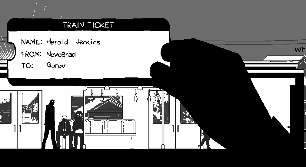
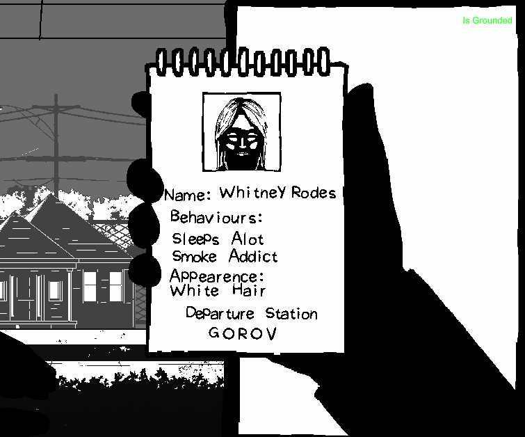
Some NPCs are traitors that must be caught. Based on the profiles that describe the behaviours and appearances of each traitor that are given to the player on a notepad, the player must check the suspected traitor’s ticket and allocate the station they’ll get off at on the given profile. I hope that makes sense.
Currently I have 5 NPC types. Tourist, Glasses Lady, Tradie, Businessman and Necklace Lady. There’s quite a few things established about how NPCs behave and the sort of data that I need to generate for the player.
    [Flags] public enum Behaviours
    {
        Nothing = 0,
        Frequent_smoker = 1 << 0,
        Takes_naps = 1 << 2,
        Always_hungry = 1 << 3,
        Listens_to_music = 1 << 4,
        Lots_of_phone_calls = 1 << 5,
        Enjoys_reading = 1 << 6,
    }
First is behaviour. Each NPC type acts out a mix of unique and generic behaviours. As an example, almost all NPC types sleep, however only the businessman and tradie takes phone calls. I made a firm rule that each NPC instance only acts out two of the however many behaviours that are designated to the NPC type. This is to prevent the situation where an NPC who isn’t a traitor which I dub “bystanders” don’t have the same behaviours and appearances as the traitors. I can see how this would be unfair for the player. The two selected behaviours are randomised upon instantiation of the NPC. I also ensure the behaviour combinations are unique to each NPC by selecting from a pool or structs that I dub “NPCProfile”.
    [Serializable] public struct NPCProfile
    {
        public string fullName;

        public int startStationIndex;
        public int exitStationIndex;

        public int npcPrefabIndex;

        public Behaviours behaviours;
        public Appearence appearence;
    }
    [Flags] public enum Appearence
    {
        Nothing = 0,
        White_hair = 1 << 0,
        Blue_collar_worker = 1 << 1,
        Has_a_cain = 1 << 2,
        Near_sighted = 1 << 3,
        Suit_and_tie = 1 << 4,
        Is_bald = 1 << 5,
        Big_boned = 1 << 6,
        Wearing_a_dress = 1 << 7,
        Wears_shorts = 1 << 8,
        Carries_a_bag = 1 << 9,
        Wears_a_hat = 1 << 10,
        Wears_a_necklace = 1 << 11,
    }
Second is Appearance. This one is quite simple. Essentially, I just need to designate a combination of appearance descriptions of each NPC prefab as they are already have predetermined appearances based on how they are drawn. Meaning, if I draw an NPC with glasses, one of the appearances selected in the inspector would be “Wears glasses”. If NPC is a traitor, that one of those appearance descriptions would appear in the notepad.
    [Serializable] public class NameData
    {
        public FirstName[] firstNames;
        public LastName[] lastNames;
    }
    [Serializable] public struct FirstName
    {
        public string gender;
        public string ethnicity;
        public string name;
    }
    [Serializable] public struct LastName
    {
        public string ethnicity;
        public string name;
    }
Third is name generation which could be a topic on it’s own. The world I’m building is based around the public transport of Melbourne. Gender and ethnicity are heavy influencers of what sort of name I generate for each NPC. The challenge is avoiding stereotypes and respecting ethnic backgrounds. For the system however, I just need to make sure I can pair these generated names to the appropriate NPC instance. I do so with the function below where I match names from a JSON file to the gender and ethnicity inputs.
private void Awake()
{
    nameData = JsonUtility.FromJson<NameData>(namesJSON.text);
}

public string GenerateName(Gender gender, Ethnicity ethnicity)
{
    string genderString = gender.ToString();
    string ethnicityString = ethnicity.ToString();
    List<FirstName> firstNamesList = new List<FirstName>();

    for(int i = 0; i < nameData.firstNames.Length; i++)
    {
        FirstName fn = nameData.firstNames[i];
        if (fn.gender.Equals(genderString, StringComparison.OrdinalIgnoreCase) &&
            fn.ethnicity.Equals(ethnicityString, StringComparison.OrdinalIgnoreCase))
        {
            firstNamesList.Add(fn);
        }
    }

    if (firstNamesList.Count == 0) return "NoFirstName";

    int firstNameIndex = UnityEngine.Random.Range(0, firstNamesList.Count);
    string firstName = firstNamesList[firstNameIndex].name;

    List<LastName> lastNameList = new List<LastName>();
    for(int i = 0; i < nameData.lastNames.Length; i++)
    {
        LastName ln = nameData.lastNames[i];
        if (ln.ethnicity.Equals(ethnicityString, StringComparison.OrdinalIgnoreCase))
        {
            lastNameList.Add(ln);
        }
    }
    if (lastNameList.Count == 0) return firstName;

    int lastNameIndex = UnityEngine.Random.Range(0, lastNameList.Count);
    string lastName = lastNameList[lastNameIndex].name;

    return firstName + " " + lastName;
}
public class StationSO : ScriptableObject
{
    public Station station_prefab;
    public int targetTrainSpeed = 100;
    public int metersPosition = 0;

    [Range(0, 1)]public float busynessFactor = 0.2f;
    public int traitorSpawnAmount = 2;

    public bool isFrontOfTrain;
    [Header("Generated")]
    public bool hadSpawned;
    public  List<NPCProfile> bystanderProfiles;
    public  List<NPCProfile> traitorProfiles;
}
Finally, the stations the NPCs start and end at are huge influencers of difficulty. If a traitor is only on the train for 1 or 2 stations, the likelihood of the player catching the traitor would be quite low. So like most procedural generation systems, fairness and variety need to be balanced. I treat each station as an NPC spawner so I can influence the distribution of NPCs. Some stations can be more busy than others, which reflects real world patterns.
public class Station : MonoBehaviour
{
    public StationSO station;
    ...
    private void SpawnNPCs()
    {
        for (int i = 0; i < station.bystanderProfiles.Count; i++)
        {
            NPCProfile bystanderProfile = station.bystanderProfiles[i];

            float randXPos = Random.Range(
            platformRenderer.renderInput.bounds.min.x + SPAWN_BUFFER,
            platformRenderer.renderInput.bounds.max.x - SPAWN_BUFFER);

            Vector3 spawnPos = new Vector3(
            randXPos,
            transform.position.y + 0.1f,
            platformRenderer.transform.position.z);

            NPCBrain bystander = Instantiate(
            trip.npc_prefabsArray[bystanderProfile.npcPrefabIndex],
            spawnPos,
            Quaternion.identity,
            platformRenderer.transform);

            bystander.profile = bystanderProfile;
            bystander.role = Role.Bystander;
        }

        for (int i = 0; i < station.traitorProfiles.Count; i++)
        {
            NPCProfile traitorProfile = station.traitorProfiles[i];
            float randXPos = Random.Range(
            platformRenderer.renderInput.bounds.min.x + SPAWN_BUFFER,
            platformRenderer.renderInput.bounds.max.x - SPAWN_BUFFER);

            Vector3 spawnPos = new Vector3(randXPos,
            transform.position.y + 0.1f,
            platformRenderer.transform.position.z);

            NPCBrain traitor = Instantiate(
            trip.npc_prefabsArray[traitorProfile.npcPrefabIndex],
            spawnPos,
            Quaternion.identity,
            platformRenderer.transform);

            traitor.profile = traitorProfile;
            traitor.role = Role.Traitor;
        }
    }
    ...
}
How I like to code is very data oriented based. I rely serialized data, static APIs and limited classes to avoid dependencies and cross references. I have a video explaining a bit more in depth as to why. Here I want to talk more about the how.
I start off with the NPC component I call “NPCBrain”. Just for context I call my state machines “Brains” hence the name. The goal I have here as a programmer is to keep the NPC object script in one script. Following my video I linked above, I create a basic switch case state machine. Despite the NPCBrain having many states, the logic to get to each state is very simple. Considering the “Behaviours” enum is a bitmask, I just need to match the current behaviour to one of the behaviour enum flags using an AND operator.
 ... else if ((curBehaviour & Behaviours.Frequent_smoker) != 0)
 {
     SetState(NPCState.Smoking);
 }
 else if ((curBehaviour & Behaviours.Takes_naps) != 0)
 {
     SetState(NPCState.Sleeping);
 }...
When the bitwise result isn’t zero, I set the state. An advantage I found, that is different to how state machines are regularly taught, is decoupling the animations from the states. I can see, that overtime, the states and animations will grow. To reduce the amount states needed, I can couple animations like “sitting eating” and “standing eating” into one “Eating” state. Each state already has access to the first frame, every frame, every fixed frame and the last frame of the being the state so handling the further logic to decide which animation to play can be stored in those scopes. I’ll also take advantage of the simplification that comes with being on a train. NPCs are either standing or sitting for most behaviours so a simple check on whether the NPC is designated a seat will determine which of the animations to play.
        switch (curState)
        {
            ...
            case NPCState.Eating:
            {
                stateDuration = UnityEngine.Random.Range(
                npc.pickBehaviourDurationRange.x,
                npc.pickBehaviourDurationRange.y);

                if (chairPosIndex != int.MaxValue)
                {
                    curClip = atlas.clipDict[(int)NPCMotion.SittingEating];
                }
                else
                {
                    curClip = atlas.clipDict[(int)NPCMotion.StandingEating];
                }
            }
            break; ...
        }
Onto to the behaviour selection logic, I want the NPCs to randomly choose the next behaviour on a timer. The timer value is also randomly selected from a range each time the NPC enters into a new random behaviour state. I have to consider that this logic influences two paradigms, difficulty and naturalness. If the NPC takes a long to change behaviours, the information is more limited to the player. If the range of the timer value is too small, the more robotic the NPC will appear to be. It is too soon to tell where the sweet spots are for these values, but I can tell I will need control here when level designing.
private Behaviours[] behaviourFlags;
private Behaviour curBehaviour
private void UpdateStates()
    {
        switch (curState)
        {
            ...
            case NPCState.Eating:
            {
                if (behaviourClock  > stateDuration)
                {
                    curBehaviour = PickBehaviour();
                }
            }
            break;...
        }
    }

    private Behaviours PickBehaviour()
    {
        return behaviourFlags[UnityEngine.Random.Range(0, behaviourFlags.Length)];
    }
There is also logic outside of behaviours every NPC needs. They all need to be able to find a slide door, board the train, find a seat, find a standing position and exit the train. The challenge here is CPU optimisation. I want a lot of NPCs existing at once. A pattern here is each function calculates a position for the NPC to move towards. Considering the train doesn’t move in world space, these world positions can be cached beforehand to minimise spikes in performance. Lets take for example the FindSlideDoor() method.
    private void FindSlideDoor()
    {
        float shortestDist = float.MaxValue;
        float selectedSlideDoorPos = float.MaxValue;
        for (int i = 0; i < trainStats.slideDoorPositions.Length; i++)
        {
            float dist = Mathf.Abs(trainStats.slideDoorPositions[i] - transform.position.x);

            if (dist < shortestDist)
            {
                shortestDist = dist;
                selectedSlideDoorPos = trainStats.slideDoorPositions[i];
            }
        }
        targetXPos = selectedSlideDoorPos;
        curPath = Path.ToSlideDoor;
    }
The goal here is to find the closest SlideDoor object. Instead of querying each slide door position individually, I cache every slide door’s x position into a float array stored in a scriptable object trainStats.slideDoorPositions and I can loop through those values instead.
    private void SetSlideDoorPositions()
    {
        int slideDoorsPerCarriage = carriages[0].exteriorRenderers.Length;
        int totalSlideDoors = carriages.Length * slideDoorsPerCarriage;

        stats.slideDoorPositions = new float[totalSlideDoors];

        for (int i = 0; i < carriages.Length; i++)
        {
            Carriage carriage = carriages[i];

            for (int j = 0; j < carriage.exteriorSlideDoors.Length; j++)
            {
                int curIndex = i * slideDoorsPerCarriage + j;
                stats.slideDoorPositions[curIndex] = carriage.exteriorSlideDoors[j].transform.position.x;
            }
        }
    }
This is cheaper because it avoids the overhead of interacting with scene objects at runtime which are scattered in memory. Float arrays are contiguous, making iterations to find the closest position much faster. I use the same technique for the other methods too. The con is obviously there’s more arrays to create, paying the upfront cost either in edit time or in the first frame. During runtime, I’m set to maximise my NPC amount with a less performance cost in comparison.
The final framework allows me to scale in a specific way that serves the overall game loop. NPCs hold a duality of purpose, giving hints to the player and world building. Later on, the plan is to create specific NPCs that hold more of a narrative purpose. I plan to have a sports event happen and so the train would be full of sports fans. The framework should support this idea. Sports fans would have sport fan behaviours such as chanting, drinking etc. NPCs interacting with each other is another avenue I want to explore as well which I hope to help further build a convincing world. The idea would be to set the target position to another NPC, once close enough, enter the conversation state and talk until the behaviour timer stops. The framework should hold… I hope. We’ll see how we go.
Thank you for reading.
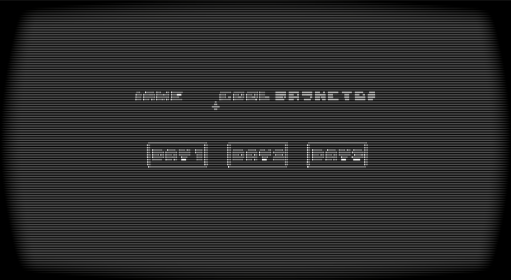
This shader was all about simulating CRT technology with the challenge of being as accurate as possible. It turns out it is just a combination of smaller effects and for a 4 week project this fit the scope well.
The electron beam of a CRT screen doesn’t naturally travel in a straight line which is why the screen shape is warped. CRT screens usually have a vignette around the edges to minimise the noticeable curve of the screen. Heres how I did it:
float3 CRTCoordsAndSDF(float2 p, float2 screenParams, float vignetteWidth, float warpOffset)
{
    float2 centredUV = p * 2 - 1;
    float2 warpUV = centredUV.yx / warpOffset;
    float2 uv = centredUV + centredUV * warpUV * warpUV;
    uv = uv * 0.5 + 0.5;

    if (uv.x <= 0.0f || 1.0f <= uv.x || uv.y <= 0.0f || 1.0f <= uv.y) uv = 0;

    float2 vignette = vignetteWidth / screenParams.xy;
    vignette = smoothstep(0, vignette, 1 - abs(uv * 2.0f - 1.0f));

    float vignetteSDF = saturate(vignette.x * vignette.y);

    return float3(uv, vignetteSDF);
}
To get a curve I squared the warped UV and added back to the centred UV. I combined both the vignette and warped UV because the vignette needed the calculated UV. It was just cheaper that way. I cull out anything outside the the 0-1 range to get the shape. The UV ends up looking like this:
Scanlines are due to the horizontal raster scanning of the CRT laser beam. The laser rapidly scans one line at a time. The area between each line remain darker causing this scanline effect. I wanted control over the scanline amount and fall off. The function I use here is quite short and simple, but it does the job.
float ScanLines(float rawScale, float colValue, float scanLineFallOff)
{
    return colValue * pow(distance(frac(rawScale), 0.5), scanLineFallOff);
}
The input colValue will be the greyscale of the blit texture. This is too get brightness as a factor of the line width as brighter colours will yield thinner lines due to the bloom and colour bleeding they cause.
During the 1980s-1990s, broadcast television tend to use YIQ as a colour space. Y is the luminance and IQ is the chrominance. Using this colour space will constrain the colours I have available based on what was available during this period.
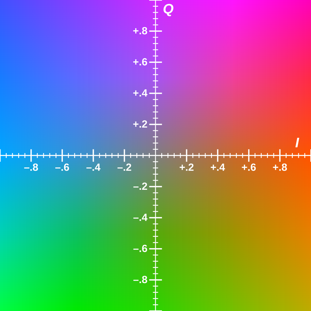
float3 YIQColorGrading(float3 color, float cyanToRed, float magentaToGreen, float brightness)
{
    float3x3 RGBToYIQ = float3x3(0.299, 0.596, 0.211,
                                 0.587, -0.274, -0.523,
                                 0.114, -0.322, 0.312);

    float3x3 YIQToRGB = float3x3(1, 1, 1,
                                 0.956, -0.272, -1.106,
                                 0.621, -0.647, 1.703);

    float3 colParams = float3(brightness, cyanToRed, magentaToGreen);
    float3 crtConversion = float3(0.9, 1.1, 1.5);

    float3 final = mul(color, RGBToYIQ);
    final = colParams + (crtConversion * final);

    return mul(final, YIQToRGB);
}
I found the calculations to get to YIQ on the wikipedia page . This function allows me to colour correct in the Unity scene and still output RGB values. The YIQ parameters are also public for me to use in the Unity Scene.

Chromatic Aberration occurs as the electron beams age. Each beam of a CRT is either red, green or blue and all must hit the same physical point on the screen. When the accuracy wears off chromatic aberration starts to occur. These beams were prone to bloom sensitive, where lighter colours bled into neighbouring phosphor dots (CRT version of pixels). Unity’s default bloom shader sufficed well so I won’t go into much detail about that. One thing I’ll say is to replicate the CRT sensitivity, I lowered the bloom threshold. To achieve the chromatic aberration effect, I sampled the blit texture three times, each with an offset controlled in the Unity scene. One channel of each blit texture was added to a new float3, creating a similar camera texture, but with each RGB channel slightly offset from the centre of the screen.
            float chromABias = length(crtUV * 2 - 1) * _chromaticAberationIntensity;
            float3 chromCol = float3(0,0,0);
            for (int i = -offset; i <= offset; i++)
            {
                float o = chromABias * i;
                float2 uv = crtUV.xy + o;

                float4 blit = SAMPLE_TEXTURE2D_X(_BlitTexture, point_clamp_sampler, uv);
                float3 col = YIQColorGrading(blit, _cyanToRed, _magentaToGreen, _brightness);

                if (i== -offset)
                {
                    chromCol.x += col.x;
                }
                else if (i == 0)
                {
                    chromCol.y += col.y;
                }
                else
                {
                    chromCol.z += col.z;
                }
            }
Broadcast signals were prone to being unstable at times causing signal static. I use a vertical scrolling sinewave with a high frequency that changes in amplitude randomly.
float SignalSDF(float2 p, float time, float range, float freq, float mag ,float bias)
{
    float mask = 1 - saturate(range * distance(p.g, 1 - frac(time * 0.5)));

    float sinIn = freq * p.g;

    float b = 1 + (mask * mag * sin(sinIn));

    float wave = 1 - saturate(distance(p.r, b));

    float flooredTime = floor(time * 10);
    float normRandRange = Hash21(flooredTime.xx);
    float flicker = round(bias * normRandRange);

    float t = mask * wave * flicker;

    float sdf = lerp(1, 0.9, t);
    return sdf;
}
I want it to snap in an out so I floored time and put it through a Hash21 I have which will output a random value between 0-1. The bias controls how frequently the static shows on the screen.
This is the final product. All fairly simple techniques here where research is the driving force for quality.

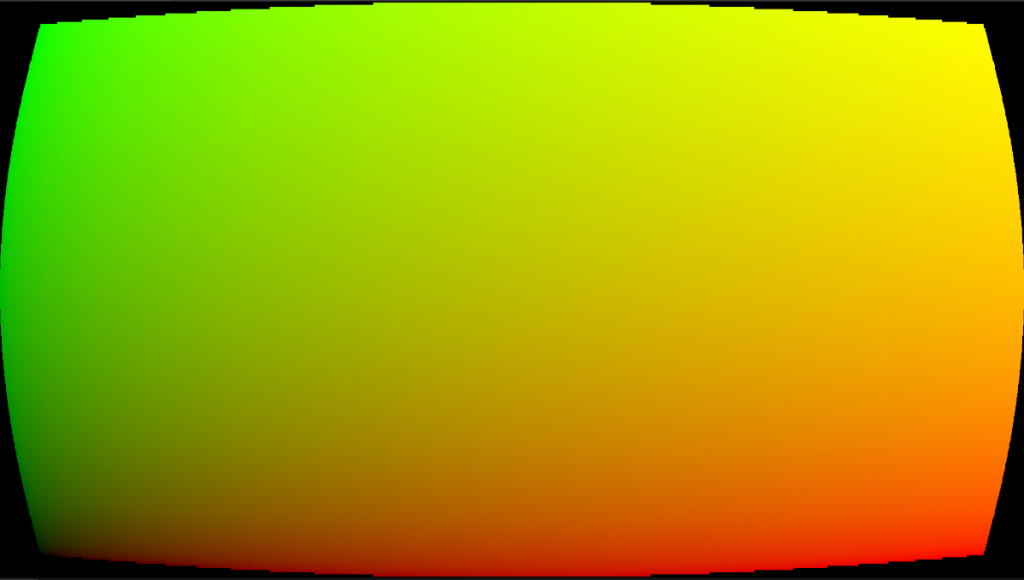
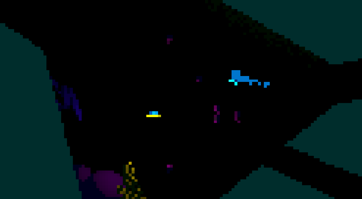
The idea behind this game is to simulate the deep sea in an abstract fashion. 80% to 90% of screen is pitch black and the colours are all on a large grid that can move with player abilities. The challenge was to still make the game legible, working with these quite extreme constraints.
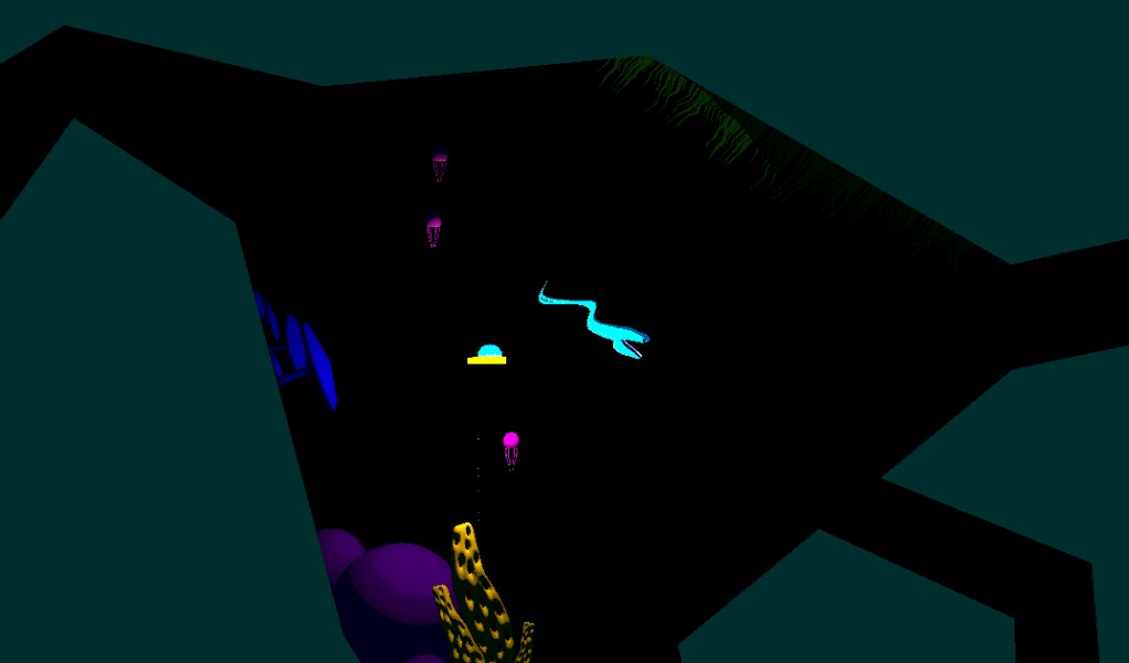
This is how the scene is set. I Use the 3D render pipeline and an orthographic camera. Every material uses a flat colour and a simplified custom lighting model where all I use is the distance attenuation, and light direction to render light. This is all done in shader graph using a custom function.
void BasicAdditionalLights_half(float3 WorldPosition, float3 WorldNormal, out float TotalAttenuation, out float3 LightColor)
{
    TotalAttenuation = 0.0;
    LightColor = float3(0, 0, 0);

#ifndef SHADERGRAPH_PREVIEW
    uint pixelLightCount = GetAdditionalLightsCount();
    LIGHT_LOOP_BEGIN(pixelLightCount)

    uint perObjectLightIndex = GetPerObjectLightIndex(lightIndex);
    Light light = GetAdditionalPerObjectLight(perObjectLightIndex, WorldPosition);

    float atten = light.distanceAttenuation;

    float NdotL = saturate(dot(WorldNormal, light.direction));

    float diffuse = atten * NdotL;
    TotalAttenuation += diffuse;
    LightColor += light.color;
    LIGHT_LOOP_END

#endif
}
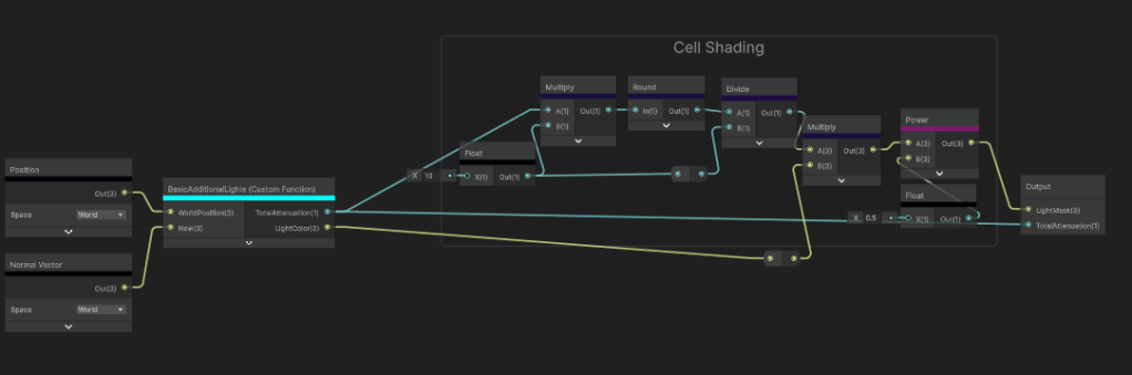
Too simplify it even further I use basic cell shading to get as few colours as possible for the post processing filter. Legibility is my number one priority here.
Onto the post processing, I use a Custom Render Feature because the shader I create is not possible in shader graph and optimisation is a huge factor particularly for this game.
        float4 calc(Varyings input) : SV_Target
        {
            float2 screenPos = float2(_ScreenParams.x, _ScreenParams.y);
            float2 scaledAspectRatioUV = screenPos / _gridScale;

            float2 scaledTexCoord = input.texcoord * scaledAspectRatioUV;
            float2 id = round(scaledTexCoord);
            float2 gridTexCoord = id / scaledAspectRatioUV; // quantized UV
            float4 blit = SAMPLE_TEXTURE2D_X(_BlitTexture, point_clamp_sampler, gridTexCoord);
            return blit;
I start off quantising the camera colour to retrieve this output.
Already looking tough to see. The reason why the cells need to be so big is because a black grid will need to be rendered over the top of it. Now making a grid is fairly simple and I got a video tutorial for it here. The real challenge is moving each grid cell without it loosing its square shape.
I use a compute shader to render a render texture that my post processing shader can sample.
[numthreads(8, 8, 1)]
void CSMain(uint3 id : SV_DispatchThreadID)
{
    float2 aspScreen = aspectRatioPentile(_Resolution);
    float2 uv = (float2(id.xy) + 0.5) / _Resolution;

    float2 scaledAspectRatioUV = _Resolution / _gridScale;
    float2 scaledTexCoord = uv * scaledAspectRatioUV;

    float2 idCoord = round(scaledTexCoord);
    float2 gridTexCoord = idCoord / scaledAspectRatioUV;

    float2 gridSpacePlayerPos = (_playerPos * _Resolution) / _gridScale;

    float centerLight = circleSDF(gridTexCoord, aspScreen);
    float sonarPing = sonarSDF(gridTexCoord, aspScreen, 0, 0.5);
    float flare = flareSDF(gridTexCoord, aspScreen, 20, 2) * 50;
    float radialScan = radialScanSDF(gridTexCoord, aspScreen, 1, 1) * 10;
    float col = 0;
    int neighbourRange = 4;
    for (int x = -neighbourRange; x <= neighbourRange; x++)
    {
        for (int y = -neighbourRange; y <= neighbourRange; y++)
        {
            float2 offset = float2(x, y);
            float2 localTexCoord = scaledTexCoord - offset;
            float4 currSC = float4(frac(localTexCoord), floor(localTexCoord));

            float2 localUV = (currSC.zw) / scaledAspectRatioUV;
            float sonar = sonarSDF(localUV, aspScreen, 0, 2);
            float flare = flareSDF(localUV, aspScreen, 20, 2) * 4;
            float radialScan = radialScanSDF(localUV, aspScreen, 1, 5);

            float totalMask = sonar + flare + radialScan;

            float2 displacementDir = normalize(gridSpacePlayerPos - currSC.zw);
            float2 displacedPos = currSC.xy + offset + (displacementDir * totalMask);
            float currDistFromSquare = max(-(max(abs(displacedPos.x) - 0.5, abs(displacedPos.y) - 0.5)), 0);
            col += currDistFromSquare;
        }
    }
    float totalMask = saturate(centerLight + sonarPing + flare + radialScan);
    col = smoothstep(_gridThickness, 1 - _gridThickness, col);
    col *= totalMask;
    col = step(0.01,col);
    Result[id.xy] = float4(col, totalMask, 0, 0);
}
The way this compute shader works is I quantise the UVs to the same size as the post processing and create a mask for each type of ability that I will show later. For context I have the “Flare”, “Radial Scan” and “Sonar Ping” abilities. I make each of the SDFs and combine them all in one single mask. Then I loop through a 2D array with “offset” being each index and use that to calculate the direction the grid cell should be moving. The ability SDFs I generate determine the distance the cell will move. The larger the 2D array, the further the grid cell can travel before being culled.
It works as intended, however there is a great cost. The red flag for me is the nest for loop. Unfortunately I couldn’t find anyway of avoid the nest for loop considering I rely on a 2D array to control the direction. Along with keeping both the grid and square cell intact, made for a huge challenge. Keeping the neighbouring samples around 4 was a good balance between performance and effectiveness. Here are the other two abilties in the render texture form:
Now the mask is done I can use render texture as a multiplying factor in the UV for the blit texture.
Heres the final result with all three abilities:
In the end this was a quick solo project that tested my current capabilities as a tech artist. I feel like I stretched the what can be done here with these aesthetic and hardware limitations. For what looks to be a simplistic looking game, there’s a lot that happens underneath!
Fog of War
I use a compute shader to read and write to a world-space render texture. The compute shader is given the player’s world-space position in relation to the size of the render texture and a radius value to measure the value of each texel. I use the temporal accumulation technique to compare the previous frame’s result to the calculated result and get the maximum value between the two. This render texture is sampled on the mini map and in the post processing. I use two colour palettes to resemble the player’s current area and the uncovered area. The player’s current area uses light neutral tones and uncovered area uses a deep blue filter. The mini map is handled the same way but in shader graph.It samples a regular 2D texture of a top down view of the entire map and I apply the render texture over the top.
[numthreads(8, 8, 1)]
void CSFogOfWar(uint3 id : SV_DispatchThreadID)
{
    if (id.x >= _TextureSize || id.y >= _TextureSize) return;

    float4 current = FogOfWarResult[id.xy]; //Previous Texture
    float2 worldPos = float2(id.xy);
    float dist = distance(worldPos, _ScaledPlayerPos.xz);
    float playerArea = pow(saturate(1 - (dist / _RevealRadius)), 0.5);
    //Temporal Accumulation
    float uncoveredArea = max(current.g, playerArea);

    FogOfWarResult[id.xy] = float4(playerArea, uncoveredArea, 0, 0);
}
Falling Walls
For context, this was the main mechanic for the game. The camera rotates to 4 angles around a circle with the player in the centre. The walls drop down and lift up depending on the players position and camera angle. This was also our solution to keeping the player visible behind walls.
The falling walls are also reading off of a sampled render texture which looks like this at runtime:
The render texture is given an offset value and the position of the opposite corner of the current room in relation to the camera. The offset value acts as a buffer to avoid covering the walls in behind the player. 0.25m was what I chose but anything greater than 0m and less than 0.5m would work too considering the width of the walls is 1m and their origins are on the mesh’s bottom centre. The corner position is the corner of the rectangle not touching the edges of the texture.
    private void UpdateBorderArea()
    {
        Vector2 center = new Vector2(RoomShapeCollider.instance.center.x, RoomShapeCollider.instance.center.z); //Current room center
        Vector2 posXZ = new Vector2(cameraData.nextCameraPos.x, cameraData.nextCameraPos.z); //The next camera position
        float camSignX = Mathf.Sign(posXZ.x - center.x);
        float camSignY = Mathf.Sign(posXZ.y - center.y);
        // Pick the opposite corner of camera
        foreach (Vector2 corner in RoomShapeCollider.instance.corners)
        {
            float cornerSignX = Mathf.Sign(corner.x - center.x);
            float cornerSignY = Mathf.Sign(corner.y - center.y);
            if (cornerSignX == -camSignX && cornerSignY == -camSignY)
            {
                activeCorner = corner * settings.squScale;
                break;
            }
        }
        //Directional Offset
        dirOffset = new Vector2(helmStats.currentPlayerPos.x, helmStats.currentPlayerPos.z) - posXZ;
        float quarterScale = settings.squScale * 0.25f; //Offset amount to use as a buffer for the rectangle
        dirOffset = new Vector2(Mathf.Sign(dirOffset.x), Mathf.Sign(dirOffset.y)) * quarterScale; // move 0.25m
        settings.hohComputeShader.SetVector(dirOffetID, dirOffset);
        settings.hohComputeShader.SetVector(activeCornerID, activeCorner);
    }
The compute shader draws the rectangle from the inputs calculated earlier. It also has to interpolate between the previous rectangle to the current rectangle so the walls don’t snap. The result is map to a -1 to 1 range so it is easier for me to move the walls both up and down.
float SDFCorner(int2 p, float2 corner, float2 offset)
{
    p += offset;
    float2 pf = p + 0.5;
    float2 diff = pf - corner;
    float dx = offset.x >= 0 ? max(diff.x, 0.0) : max(-diff.x, 0.0);
    float dy = offset.y >= 0 ? max(diff.y, 0.0) : max(-diff.y, 0.0);
    return 1 - ceil(saturate(length(float2(dx, dy))));
}

[numthreads(8, 8, 1)]
void CSBorder(uint3 id : SV_DispatchThreadID)
{
    if (id.x >= _TextureSize || id.y >= _TextureSize) return;
    float4 prev = BorderPrev[int2(id.xy)];
    float2 worldPos = float2(id.xy);
    float targetBorder = SDFCorner(worldPos, _ActiveCorner, _DirOffset);
    targetBorder = targetBorder * 2 - 1; // Remap to -1 to 1 range
    float borderArea = prev.r + (targetBorder * _BorderTime); //Interpolate between the previous rectangle to the current rectangle
    BorderResult[int2(id.xy)] = float4(borderArea, 0, 0, 0);
}
Finally the wall shader samples the render texture in the vertex pass. I use the centre of the mesh bounding box as the UV so all the vertices read same value. This is to keep the wall shape the same as it moves. The next question is how much should the walls move. My answer was the size of the walls rather than a hardcoded number. I know the origin is on the base so I get the top position of the mesh bounds and multiply it by the render texture. This is my offset value that I then subtract by the world positions of the vertices.
 v2f vert (appData v)
 {
     v2f o;
     o.origin = unity_ObjectToWorld._m03_m13_m23;
     o.offset = 0;
     o.worldPos = mul(unity_ObjectToWorld, v.position).xyz;
     #if defined(_MAPMODE_BORDER) // _BORDER is the keyword for walls
       float3 boundsSize = unity_RendererBounds_Max - unity_RendererBounds_Min;
       float2 centreBounds = (boundsSize.xz * 0.5 + unity_RendererBounds_Min.xz) / _ScaledTexelSize;
       float4 borderData = SAMPLE_TEXTURE2D_LOD(_BorderMap, sampler_BorderMap, centreBounds, 0); // Sample render texture based on the world center bounds
       o.offset = (unity_RendererBounds_Max.y) * borderData.r;
       o.worldPos.y -= o.offset; // Value between negative bounds size and positive bounds size
     #endif
...
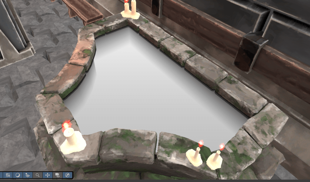
Water

Making a water shader is always a fun task and I decided to use the shader graph work flow with this one. I started off creating a procedural water noise custom function because Unity’s default voronoi noise wasn’t going to cut it. I referenced a smoke shader I found on Shadertoy. Here is my version:
void WaterHighlight_float(float2 p, float time, float foam, int samples, out float o)
{
    float2 i = p;
    float intensity = 0.005 * lerp(1, 6, foam);

    for (int n = 0; n < samples; n++)
    {
        float t = time * 3.5 / float(n + 1);
        i = p + float2(cos(t - i.x) + sin(t + i.y), sin(t - i.y) + cos(t + i.x));
        o += 1.0 / length(float2(p.x / (sin(i.x + t)), p.y / (cos(i.y + t))));
    }
    o = o / (intensity * float(samples));
    o = pow(abs(1 - o), 3);
}
Where I have to be careful here is the sample value. For a small shader, I don’t want this number to be too high. I left it as a public variable with the aim of finding the lowest value, but still having the water look good.
The foam input ended up being a nice way to add in the classic scene depth fade every other water shader usually has.
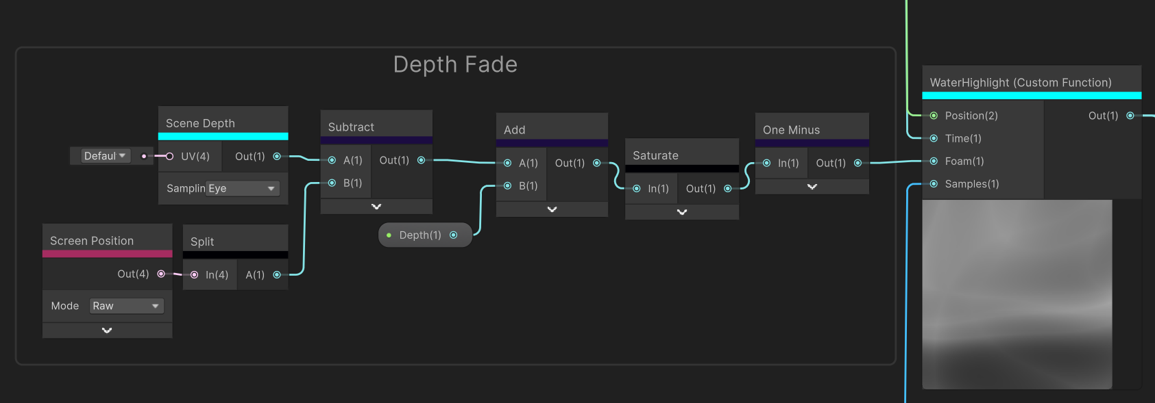
For the depth fade to work, the shader needs to be transparent. The scene depth in eye mode returns the distance of every object from the camera in meters. Subtracting this value by the A component of the raw screen position (which is the clip space distance from the camera) will result in a gradient representing object depth.
Inverting these values and using some public variables makes for a good effect for simulating water depth. Using this gradient for the foam input blends the water highlights well with it resulting in the final gradient.
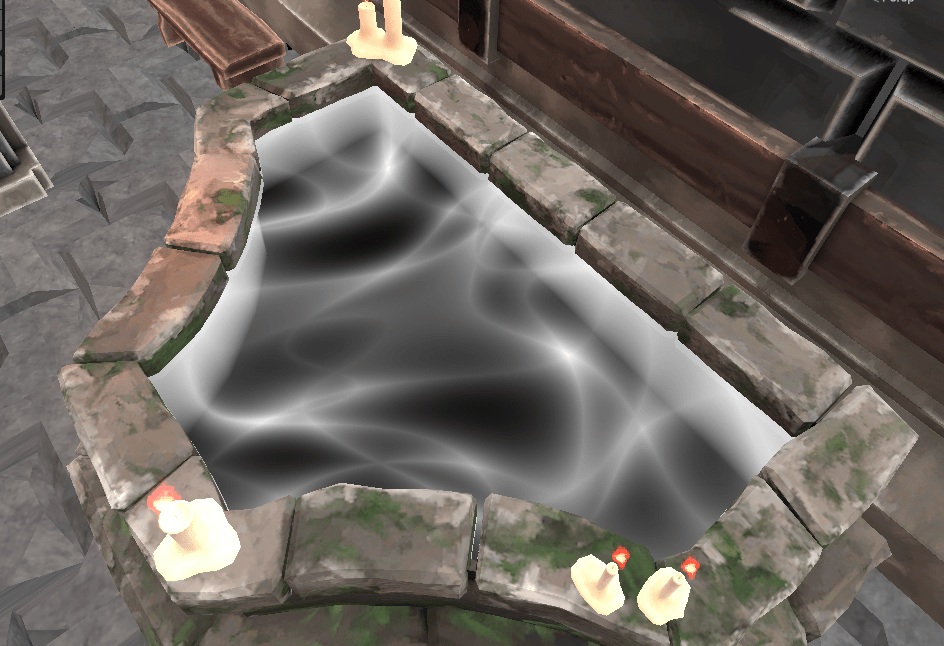

The colour gradient above is what I ended up using for the final output. These colour were very specific for Helm of Heresy, but this shader is definitely something I will use again.
FIRE
The fire is another smaller shader component to the game. I already new it was not going to be looked at closely due to the fixed large camera size, so efficiency was more on the mind. Instead of procedurally generating a noise gradient to output directly onto the material, I made a 3 by 3 atlas of sampled fire images. I found out about this technique from a GDC Talk about the development of game INSIDE.
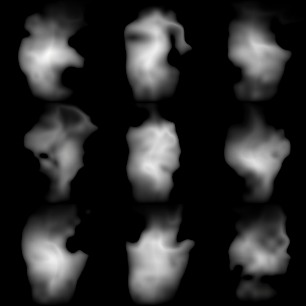
These images were generated through a normal fire shader and I just screenshotted each of them. I use a texture atlas shader that iterates through each column sequentially and each row randomly.

The reason why only the rows are random is so I can guarantee a different fire image will picked each tick.
Then I sample the same texture twice but with two different UVs, where one UV lags 1.5 seconds behind the other. This creates two alternating images of fire using the same texture.
To interpolate between the two images, I use a sine wave and normalized the scrolling frequency as a mask.

This is the last part where sampled a simple noise texture to hide the straight lines of the sine wave, multiplied the scrolling noise mask by the fire images and adding them together for the final SDF. I used have a lerp in here instead, but that yielded poor results and the snapping was quite apparent. Simply multiplying then adding to combine the two images smoothed out the transitions a lot better.
I wanted to make a quick tutorial on using render textures in Unity and why they might be useful.
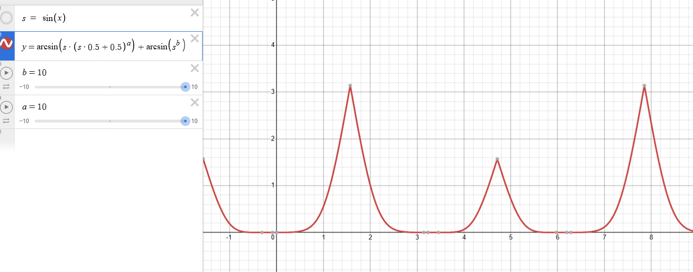
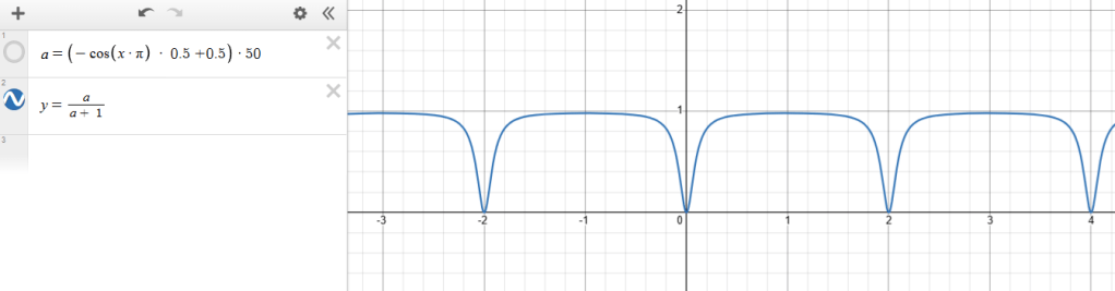
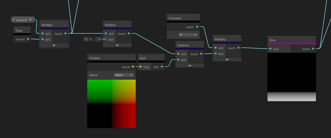
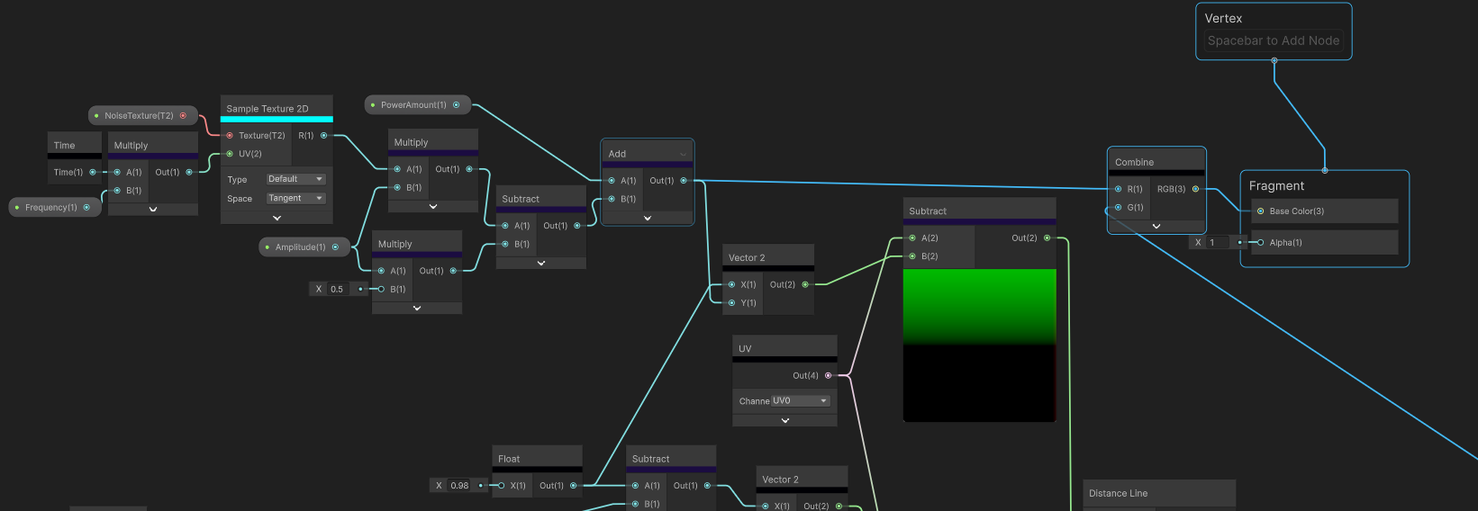
When I first started off making this shader, I started where most would start, an old fashioned Unity shader graph. It doesn’t seem too complex. Just sample a noise texture that scrolls. remap the values so the range of values is -1 to 1. then add the result to the g channel of the UV and absolute those values. Add some parameters for the amplitude, frequency and value. Here’s the shader graph:

Great!
oh no
See how the line is thinner when there’s a sudden change. That sorta sucks. The specific area of issue is this part here:
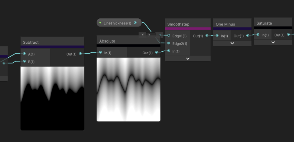
What is happening is the gradient I am outputting isn’t equal on all sides of the line. The greater the amplitude, the smaller the range between 0-1. The fix is… I don’t know… probably some crazy math that can measure the line thickness relative to the line angle. Alarm bells were ringing and I knew there was a better approach.
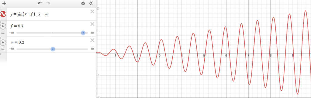
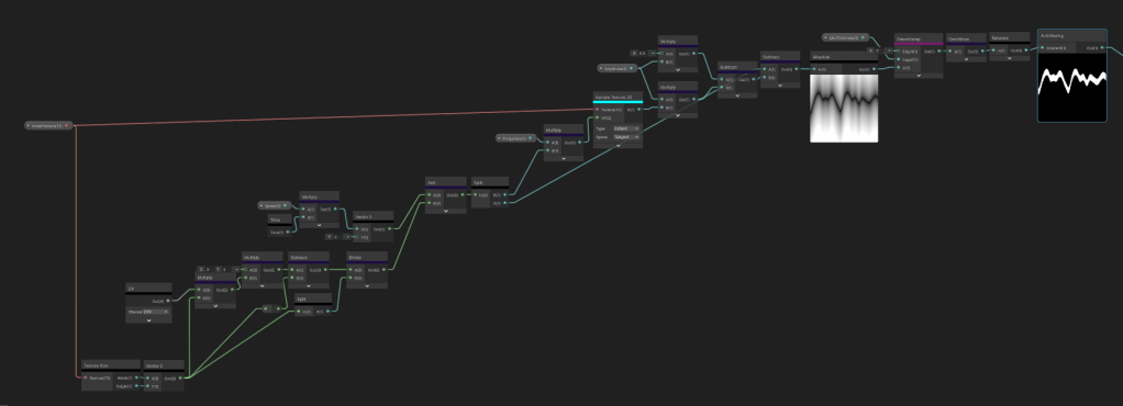
When I see this graph in action I imagine one of those lie detector machines that print these sorts of graphs.

Enter render textures. I wrote about these in my Creating a Fog of War Shader devlog but I’ll give a simple run down. Render textures are read and write textures that are built to be updated at runtime. GPU’s have frame length memory so the only way you can store data from the GPU is with a render texture.
So why would this help me?
Well like the lie detector graph, I can use a circle shape to use like a brush and scroll the render texture UV backwards. I like to call this the “brush stroke” method. The idea is because I use a circle shape, the line thickness is a consistent value no matter the direction of the line. I can use the “Temporal Accumulation” method here where I sample the previous frame result to affect the next frame result, which creates the brush stroke like effect. I mention this in my fog of war devlog too.
Unlike how I set up a render texture in the fog of war devlog, I wanted to try out the shader graph work flow instead of the code based work flow. The more I develop as a tech artist, the more I’m understanding the importance of learning both work flows.
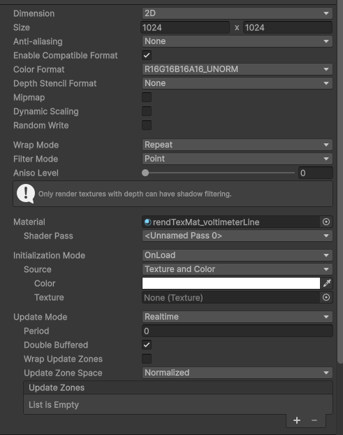
To set up you need to create a “Material”, “Custom Render Texture” in the “Rendering” tab and a “Custom Render Texture” in the “Shader Graph” tab.
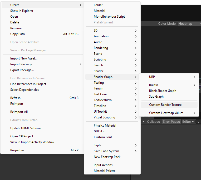
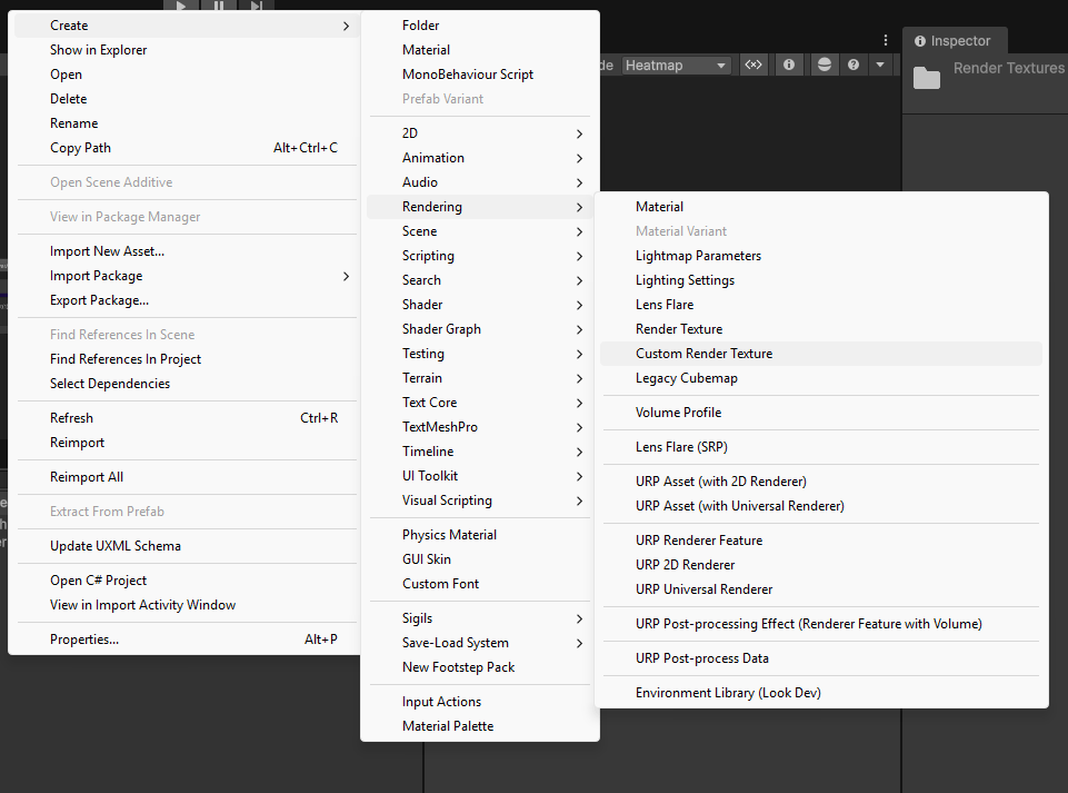
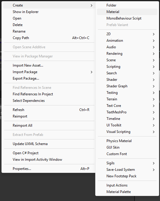
No idea why Unity decided to name them the exact same thing but at least you get different icons. I’ll call the shader version “Render Texture Shader Graph”. From here you set your custom render texture the same as you would with a normal texture until you get to the material. Initialization Mode I put as “OnLoad” and I put Update Mode as “Realtime”. This just made sense to me and I don’t see a use case where I would pick anything different. Color is the starting value of the render texture. This is important and it does depend on how your render texture shader graph works. The last important note is the “Double Buffered” option. This allows you to use the previous frame result of the render texture which is what I mentioned earlier.
Great. Now you can assign the render texture shader graph to the material and we can get started. Oh and also this render texture will need to be sampled in a regular material shader graph so you can actually see it in the game.
To get things started I like to separate everything into small easy steps and see the output in game at each step. The first step is to create a make the brush shape and put it in the correct position.
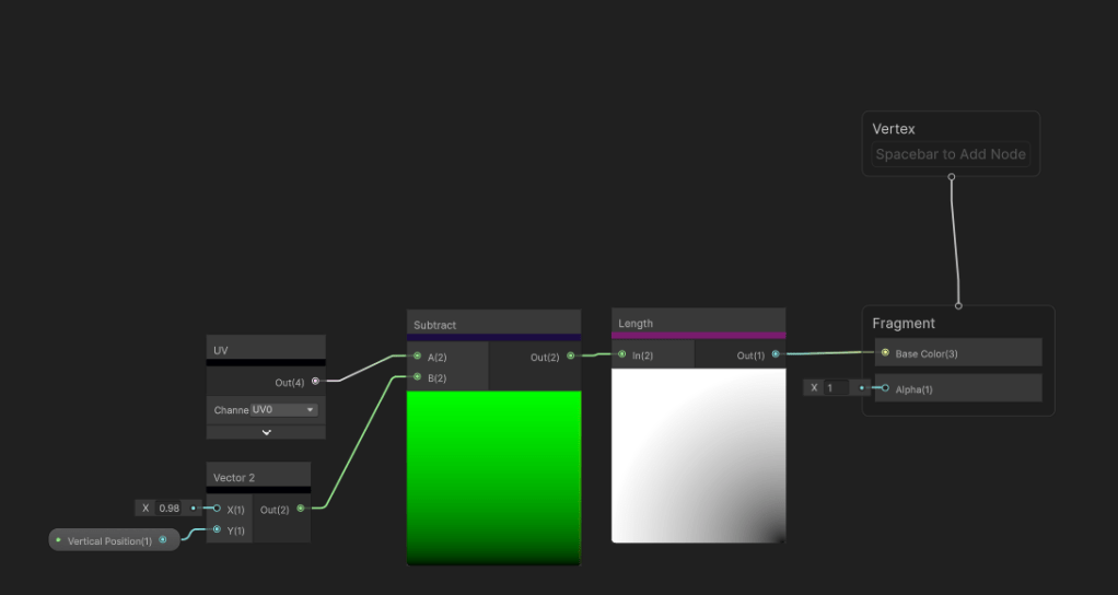
From there I scroll a noise texture to randomly offset the vertical position over time and add in some public parameters.
A little technique that I use everywhere to remapping a value cheaply is what I do with the “Amplitude” parameter. If you know the original range is between 0-1 and you want to extend the range while keeping 0 in the middle, you can multiply the parameter by the 0-1 texture, then subtract half the parameter. Say the amplitude value is 3, the result would be a range between -3 and 3. Everything else is using basic offset, scale and rounding functions for better control.
Now for the temporal accumulation.
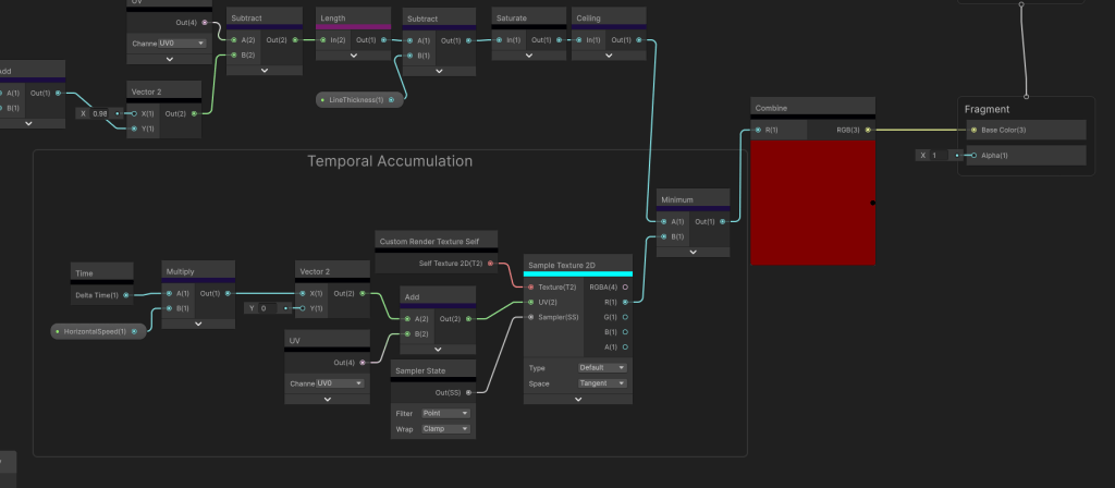
The new node for me at least is the “Custom Render Texture Self” node which is the previous frame render texture and you treat it like any other texture. It defaults to bilinear filtering even though I set the custom render texture filtering to point so I have to override that using the sampler state node. The main focus is how I set the UV. I add a very small constant value on the x axis. If I keep that a hard coded number, the graph works. Now every frame this shader will compare the calculated shader to the previous result and pick the smallest texel drawing a line. However, a very crucial and often forgotten component is adding in GPU frame independence. In other words, I don’t want the FPS to dictate the speed of the graph. Unity supplies the delta time value already. If I use that updating value instead, it will no longer matter what your FPS is, thus the graph will run at a constant speed.
Nice.
Now this is much better, but pushed to the brink, the shader still breaks.
I still get this amplitude problem. As a game dev I come to the very naturally choice between fixing it or letting it be.
I had one idea. What if instead of drawing dots, I draw lines? I already know the coordinate of each point, so just connect the dots.
I have another very handy technique I use that does exactly this. This is the sub graph I take to almost every project that I called “Distance Line”.
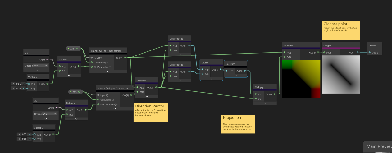
I got this math from a Shadertoy shader and I’ll admit, I still don’t quite understand the math here. I’ll link the shader below. The inputs are two UVs. The output is a linear line between the two origin points of the UVs.
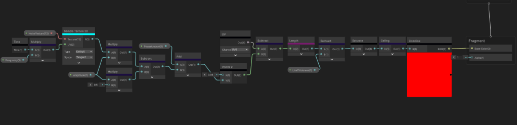
So to connect the dots, I need more information coming from the previous frame render texture or more specifically the last y value that was calculated. This is the 0-1 value that makes the brush wobble up and down randomly. I store that value directly into the R channel to use later. I also use this value to set the y origin of the next UV.
Then I get that same y value to recalculate the previous UV. These two UVs are the inputs to my Distance Line node I showed earlier.
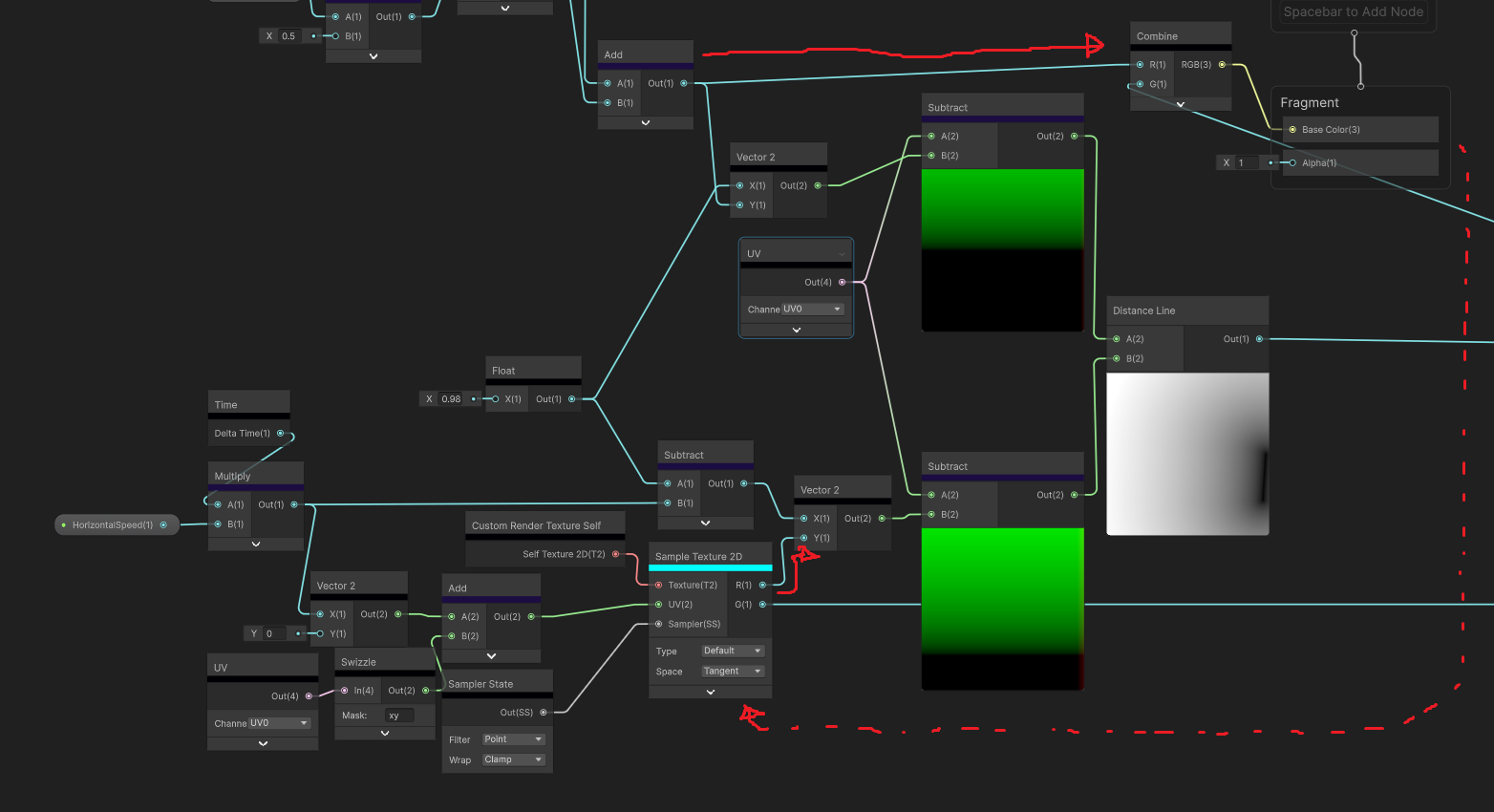
I also used the delta time value as the horizontal offset for the second UV because that is the exact x position of the tail of the line.
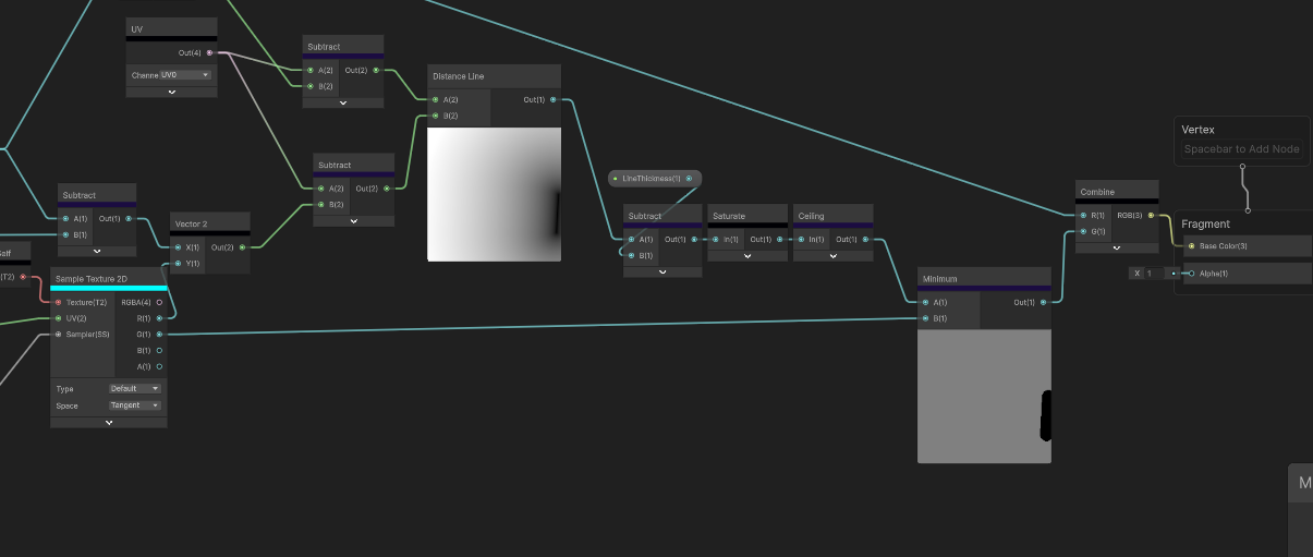
Then its just the same temporal accumulation pattern as before where I reuse the G channel.
Looks like it passes the stress test.
Its weird how often seemingly simple shaders turn into something much more complex and how they uncover hardware limitations. This is such a tiny part of this game and this game I’m making is a relatively small game. However, what lies underneath, is a whole system using a custom render texture graph that uses temporal accumulation and distance lines that is then sampled again through a material shader to output to the screen. I find this sort of stuff so fascinating, because to the player, they will never know.
Anyways, I hope to continue these blogs. As go continue my development as a tech artist. See you guys later.
Distance Line Shader: https://www.shadertoy.com/view/WddGzr


