

Fog of War
- Compute Shaders
- Post Processing
- HLSL
- Temporal Accumulation
I use a compute shader to read and write to a world-space render texture. The compute shader is given the player’s world-space position in relation to the size of the render texture and a radius value to measure the value of each texel. I use the temporal accumulation technique to compare the previous frame’s result to the calculated result and get the maximum value between the two. This render texture is sampled on the mini map and in the post processing. I use two colour palettes to resemble the player’s current area and the uncovered area. The player’s current area uses light neutral tones and uncovered area uses a deep blue filter. The mini map is handled the same way but in shader graph.It samples a regular 2D texture of a top down view of the entire map and I apply the render texture over the top.
[numthreads(8, 8, 1)]
void CSFogOfWar(uint3 id : SV_DispatchThreadID)
{
    if (id.x >= _TextureSize || id.y >= _TextureSize) return;

    float4 current = FogOfWarResult[id.xy]; //Previous Texture
    float2 worldPos = float2(id.xy);
    float dist = distance(worldPos, _ScaledPlayerPos.xz);
    float playerArea = pow(saturate(1 - (dist / _RevealRadius)), 0.5);
    //Temporal Accumulation
    float uncoveredArea = max(current.g, playerArea);

    FogOfWarResult[id.xy] = float4(playerArea, uncoveredArea, 0, 0);
}
Falling Walls
- Compute Shaders
- C#
- Vertex Shaders
- HLSL
For context, this was the main mechanic for the game. The camera rotates to 4 angles around a circle with the player in the centre. The walls drop down and lift up depending on the players position and camera angle. This was also our solution to keeping the player visible behind walls.
The falling walls are also reading off of a sampled render texture which looks like this at runtime:
The render texture is given an offset value and the position of the opposite corner of the current room in relation to the camera. The offset value acts as a buffer to avoid covering the walls in behind the player. 0.25m was what I chose but anything greater than 0m and less than 0.5m would work too considering the width of the walls is 1m and their origins are on the mesh’s bottom centre. The corner position is the corner of the rectangle not touching the edges of the texture.
    private void UpdateBorderArea()
    {
        Vector2 center = new Vector2(RoomShapeCollider.instance.center.x, RoomShapeCollider.instance.center.z); //Current room center
        Vector2 posXZ = new Vector2(cameraData.nextCameraPos.x, cameraData.nextCameraPos.z); //The next camera position
        float camSignX = Mathf.Sign(posXZ.x - center.x);
        float camSignY = Mathf.Sign(posXZ.y - center.y);
        // Pick the opposite corner of camera
        foreach (Vector2 corner in RoomShapeCollider.instance.corners)
        {
            float cornerSignX = Mathf.Sign(corner.x - center.x);
            float cornerSignY = Mathf.Sign(corner.y - center.y);
            if (cornerSignX == -camSignX && cornerSignY == -camSignY)
            {
                activeCorner = corner * settings.squScale;
                break;
            }
        }
        //Directional Offset
        dirOffset = new Vector2(helmStats.currentPlayerPos.x, helmStats.currentPlayerPos.z) - posXZ;
        float quarterScale = settings.squScale * 0.25f; //Offset amount to use as a buffer for the rectangle
        dirOffset = new Vector2(Mathf.Sign(dirOffset.x), Mathf.Sign(dirOffset.y)) * quarterScale; // move 0.25m
        settings.hohComputeShader.SetVector(dirOffetID, dirOffset);
        settings.hohComputeShader.SetVector(activeCornerID, activeCorner);
    }
The compute shader draws the rectangle from the inputs calculated earlier. It also has to interpolate between the previous rectangle to the current rectangle so the walls don’t snap. The result is map to a -1 to 1 range so it is easier for me to move the walls both up and down.
float SDFCorner(int2 p, float2 corner, float2 offset)
{
    p += offset;
    float2 pf = p + 0.5;
    float2 diff = pf - corner;
    float dx = offset.x >= 0 ? max(diff.x, 0.0) : max(-diff.x, 0.0);
    float dy = offset.y >= 0 ? max(diff.y, 0.0) : max(-diff.y, 0.0);
    return 1 - ceil(saturate(length(float2(dx, dy))));
}

[numthreads(8, 8, 1)]
void CSBorder(uint3 id : SV_DispatchThreadID)
{
    if (id.x >= _TextureSize || id.y >= _TextureSize) return;
    float4 prev = BorderPrev[int2(id.xy)];
    float2 worldPos = float2(id.xy);
    float targetBorder = SDFCorner(worldPos, _ActiveCorner, _DirOffset);
    targetBorder = targetBorder * 2 - 1; // Remap to -1 to 1 range
    float borderArea = prev.r + (targetBorder * _BorderTime); //Interpolate between the previous rectangle to the current rectangle
    BorderResult[int2(id.xy)] = float4(borderArea, 0, 0, 0);
}
Finally the wall shader samples the render texture in the vertex pass. I use the centre of the mesh bounding box as the UV so all the vertices read same value. This is to keep the wall shape the same as it moves. The next question is how much should the walls move. My answer was the size of the walls rather than a hardcoded number. I know the origin is on the base so I get the top position of the mesh bounds and multiply it by the render texture. This is my offset value that I then subtract by the world positions of the vertices.
 v2f vert (appData v)
 {
     v2f o;
     o.origin = unity_ObjectToWorld._m03_m13_m23;
     o.offset = 0;
     o.worldPos = mul(unity_ObjectToWorld, v.position).xyz;
     #if defined(_MAPMODE_BORDER) // _BORDER is the keyword for walls
       float3 boundsSize = unity_RendererBounds_Max - unity_RendererBounds_Min;
       float2 centreBounds = (boundsSize.xz * 0.5 + unity_RendererBounds_Min.xz) / _ScaledTexelSize;
       float4 borderData = SAMPLE_TEXTURE2D_LOD(_BorderMap, sampler_BorderMap, centreBounds, 0); // Sample render texture based on the world center bounds
       o.offset = (unity_RendererBounds_Max.y) * borderData.r;
       o.worldPos.y -= o.offset; // Value between negative bounds size and positive bounds size
     #endif
...
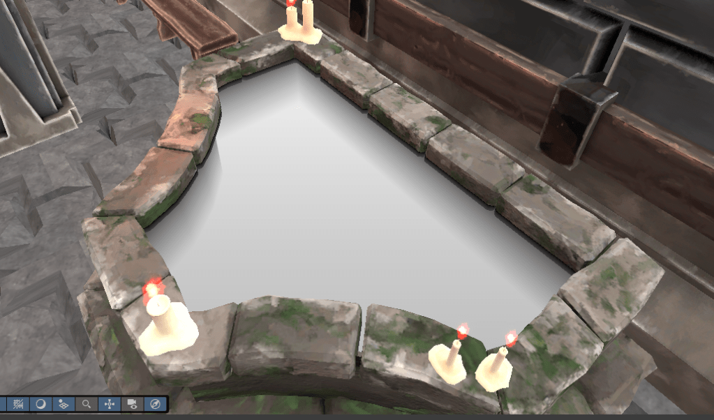
Water
- Shader graph
- Custom Procedural Noise
- Custom Functions

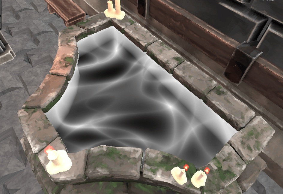
Making a water shader is always a fun task and I decided to use the shader graph work flow with this one. I started off creating a procedural water noise custom function because Unity’s default voronoi noise wasn’t going to cut it. I referenced a smoke shader I found on Shadertoy. Here is my version:
void WaterHighlight_float(float2 p, float time, float foam, int samples, out float o)
{
    float2 i = p;
    float intensity = 0.005 * lerp(1, 6, foam);

    for (int n = 0; n < samples; n++)
    {
        float t = time * 3.5 / float(n + 1);
        i = p + float2(cos(t - i.x) + sin(t + i.y), sin(t - i.y) + cos(t + i.x));
        o += 1.0 / length(float2(p.x / (sin(i.x + t)), p.y / (cos(i.y + t))));
    }
    o = o / (intensity * float(samples));
    o = pow(abs(1 - o), 3);
}
Where I have to be careful here is the sample value. For a small shader, I don’t want this number to be too high. I left it as a public variable with the aim of finding the lowest value, but still having the water look good.
The foam input ended up being a nice way to add in the classic scene depth fade every other water shader usually has.
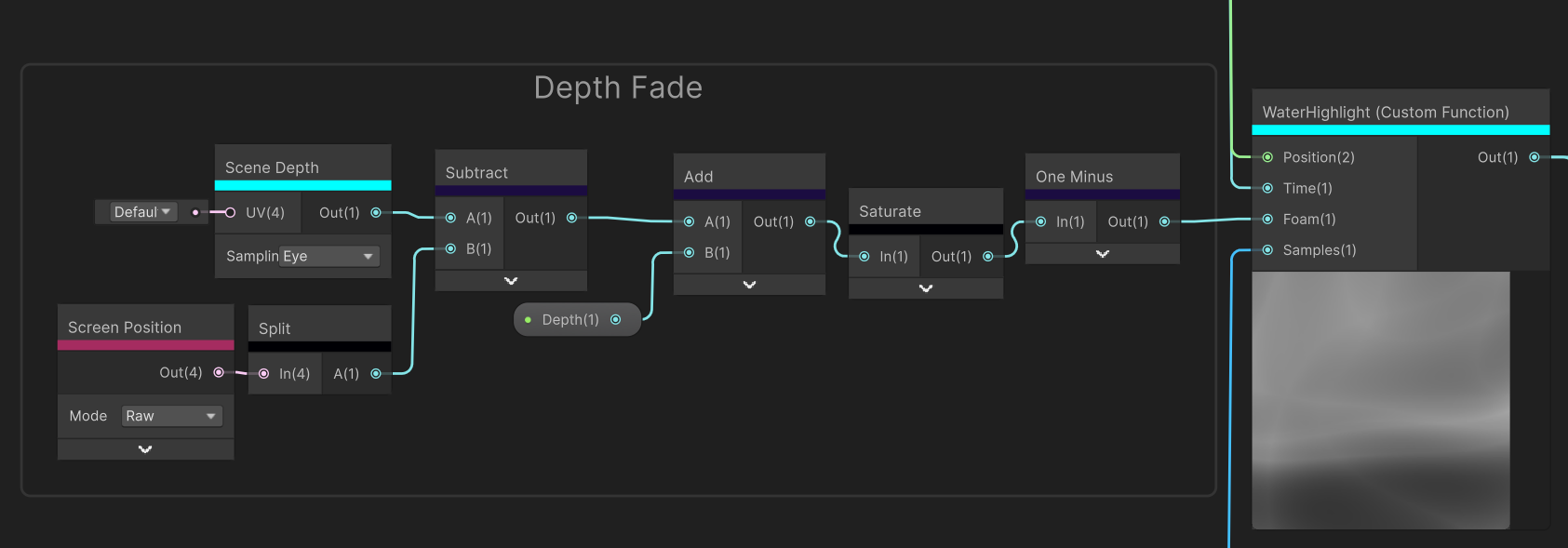
For the depth fade to work, the shader needs to be transparent. The scene depth in eye mode returns the distance of every object from the camera in meters. Subtracting this value by the A component of the raw screen position (which is the clip space distance from the camera) will result in a gradient representing object depth.
Inverting these values and using some public variables makes for a good effect for simulating water depth. Using this gradient for the foam input blends the water highlights well with it resulting in the final gradient.

The colour gradient above is what I ended up using for the final output. These colour were very specific for Helm of Heresy, but this shader is definitely something I will use again.
FIRE
- Shader graph
- Texture Atlas
The fire is another smaller shader component to the game. I already new it was not going to be looked at closely due to the fixed large camera size, so efficiency was more on the mind. Instead of procedurally generating a noise gradient to output directly onto the material, I made a 3 by 3 atlas of sampled fire images. I found out about this technique from a GDC Talk about the development of game INSIDE.
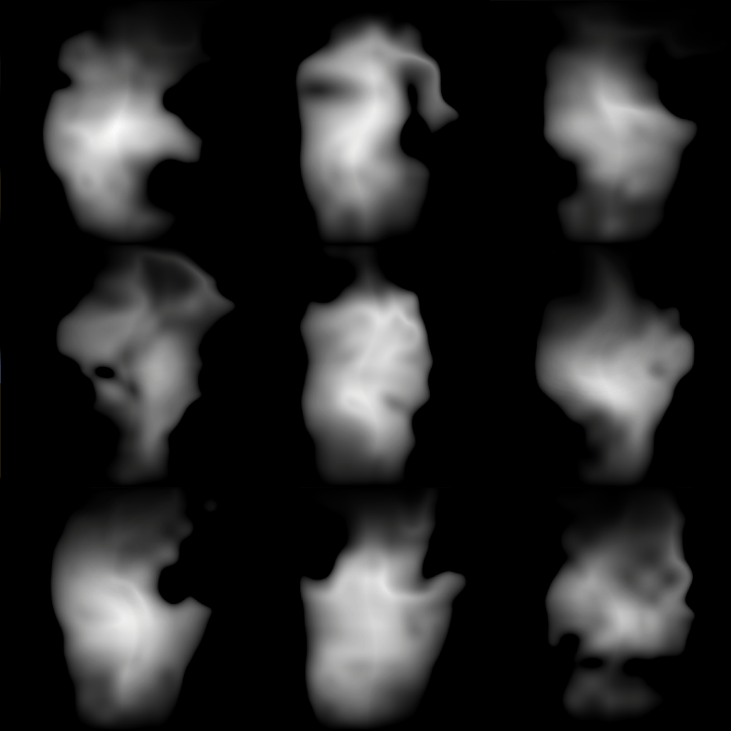
These images were generated through a normal fire shader and I just screenshotted each of them. I use a texture atlas shader that iterates through each column sequentially and each row randomly.

The reason why only the rows are random is so I can guarantee a different fire image will picked each tick.
Then I sample the same texture twice but with two different UVs, where one UV lags 1.5 seconds behind the other. This creates two alternating images of fire using the same texture.
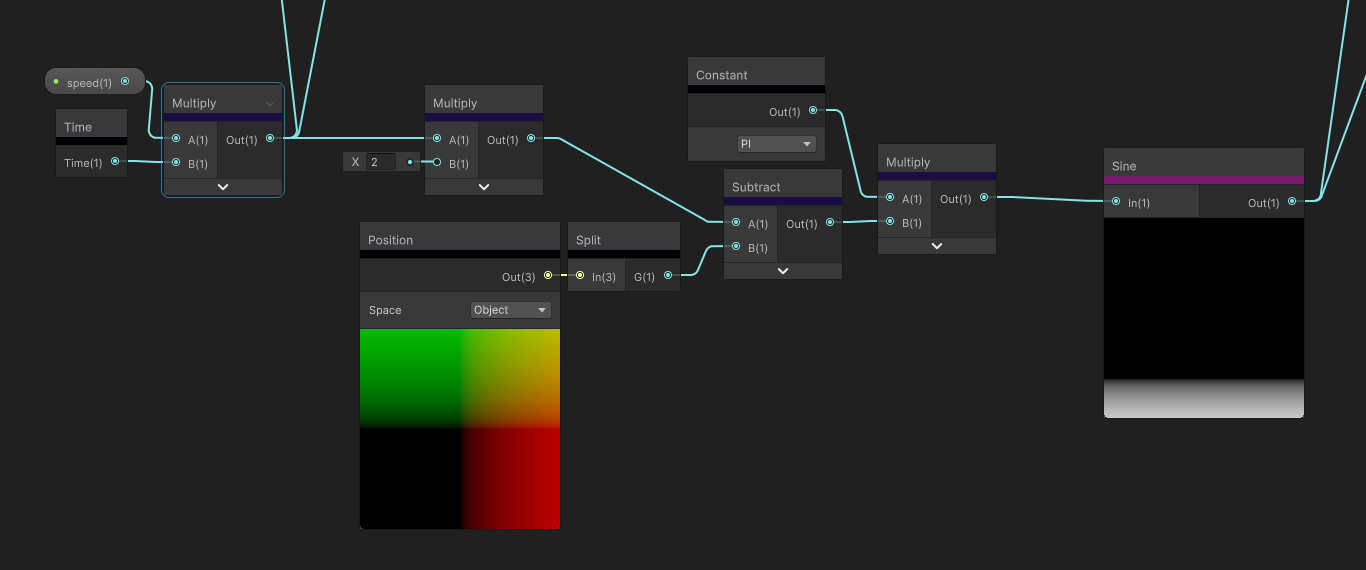
To interpolate between the two images, I use a sine wave and normalized the scrolling frequency as a mask.

This is the last part where sampled a simple noise texture to hide the straight lines of the sine wave, multiplied the scrolling noise mask by the fire images and adding them together for the final SDF. I used have a lerp in here instead, but that yielded poor results and the snapping was quite apparent. Simply multiplying then adding to combine the two images smoothed out the transitions a lot better.
